Project Copicat, Status: Complete
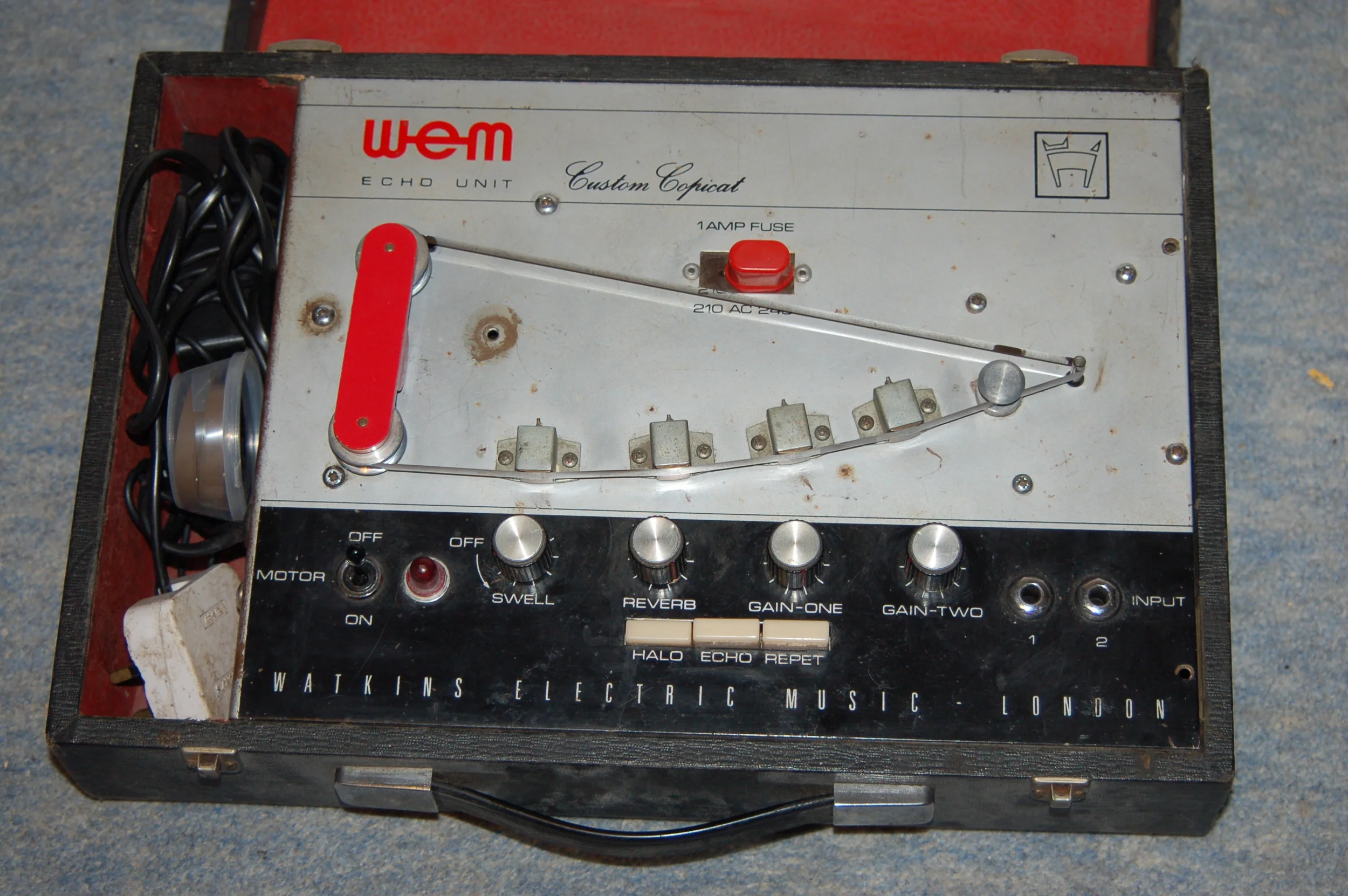
A year or two back I bought myself this Valve tape echo unit online as an impulse buy. At the time it was too much of a bargain to miss so I managed to get it for the reasonable sum of £130.00. This unit is a made by Watkins Electric Music and produced in 1966 who state that this model featured "greater stability" and "better tape transport facilities" than the previous Mk.1 and Mk.2 Valve units produced in the 1950's. In modern times one would expect to pay in the region of £500+ for a unit such as this. If indeed you can find someone willing to part with it.
For some more info on these units and spares see; here and here
And for a much more impressive rebuild of a similar Mk. 2 unit see: here
Shortly after receiving the unit and bench testing, it became apparent that this was not working as it should; the echos/repeats were present alright, but their levels were low and the burning smell which accompanied them was not very pleasant. "Time to crack it open then and see what disaster awaits me inside" I thought.
What I found...
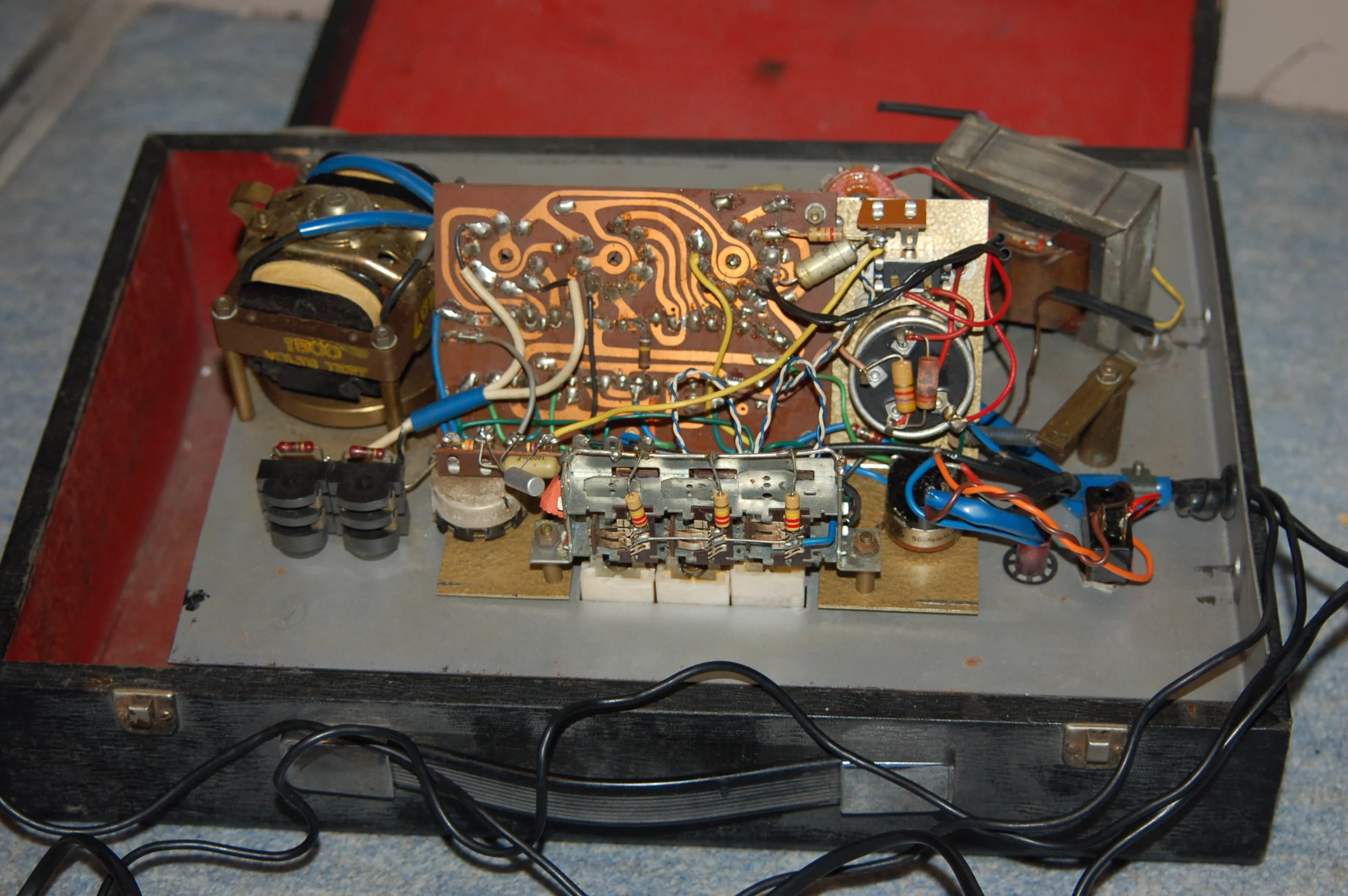
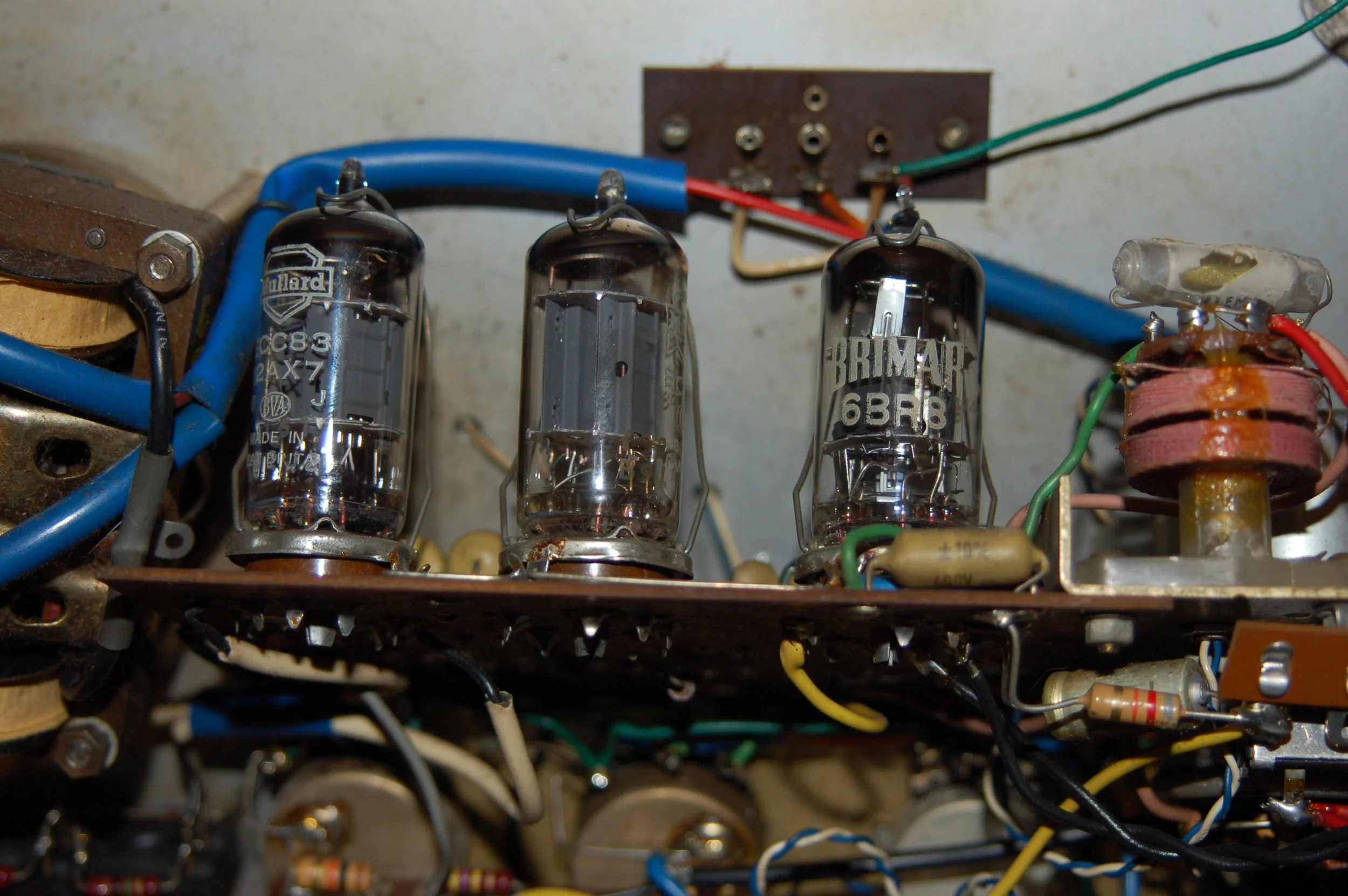
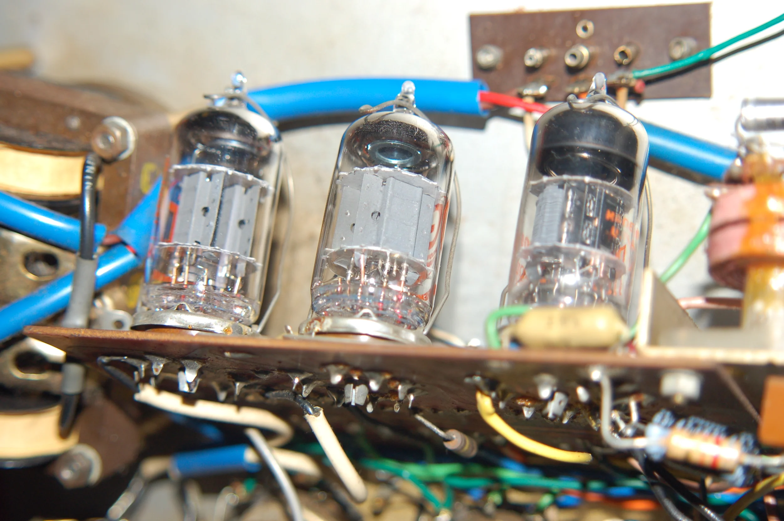
The internals of this unit actually appeared to be in very good shape, mostly, and when looking at the Valves in the unit I was greeted with a nice surprise.
Jackpot!
Inside the unit had two pretty special Valves; on the left a Mullard ECC83 Short Plate dated 1959 and centre a Mullard ECC83 F91 Long Plate produced in Blackburn in 1958. The value of these combined in good condition are equal to the price I paid for the unit. For a good breakdown on NOS (New Old Stock) Tubes/Valves, here's a good start.
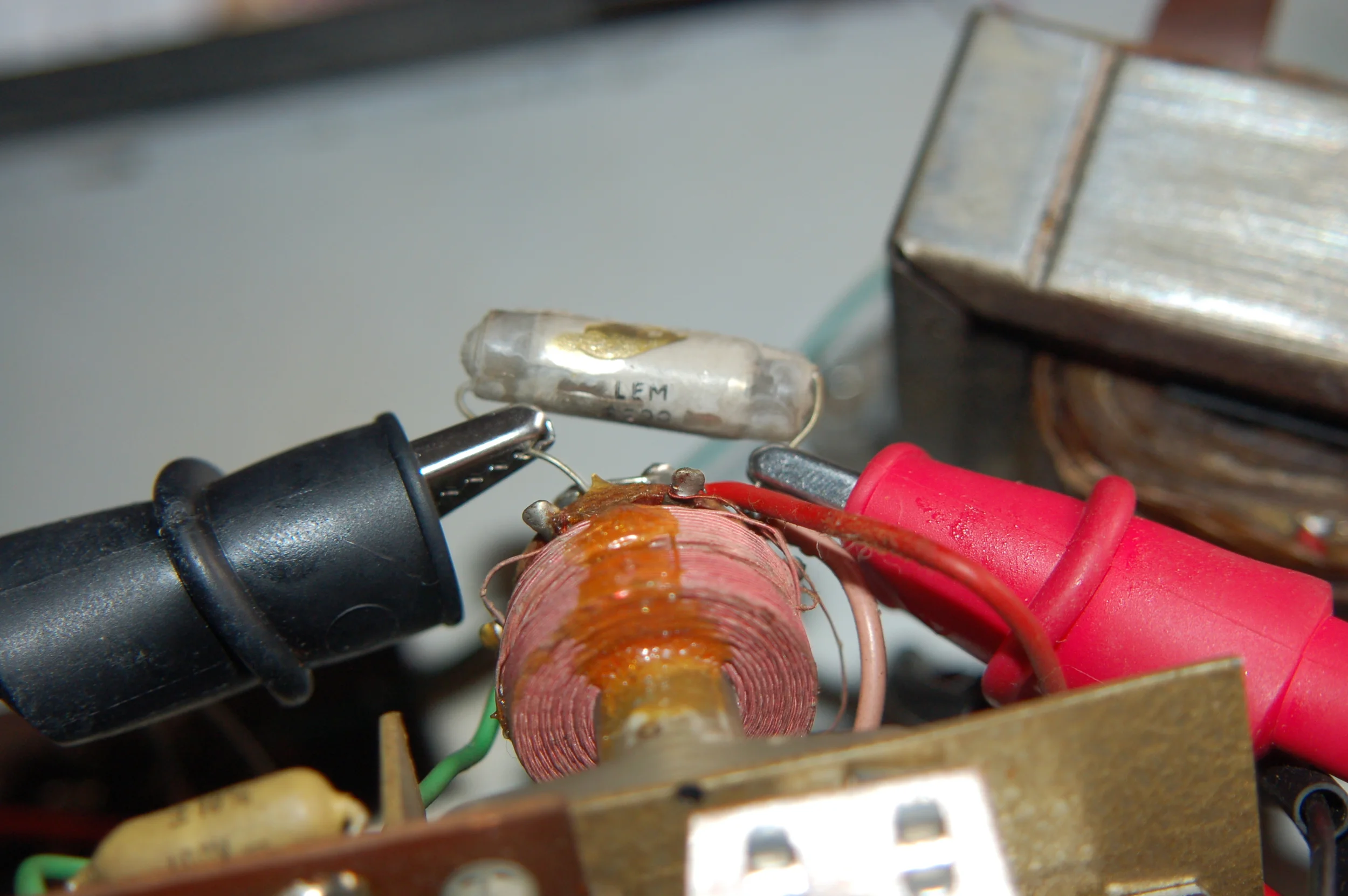
Because I was so focused on the Valves, I overlooked an obvious thing seen clearly in the right hand side of this image: The Polystyrene capacitor has failed, melted in fact.
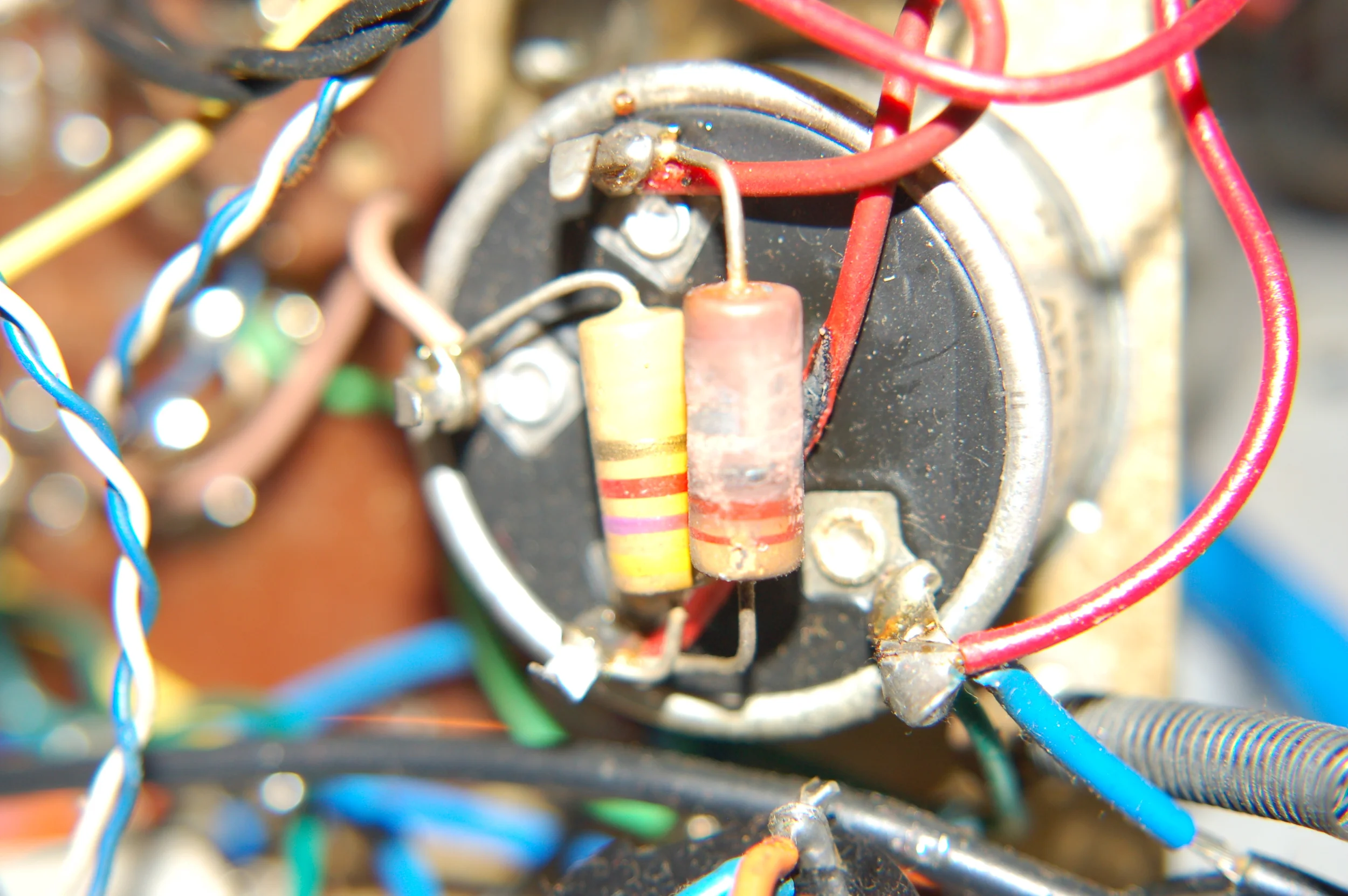
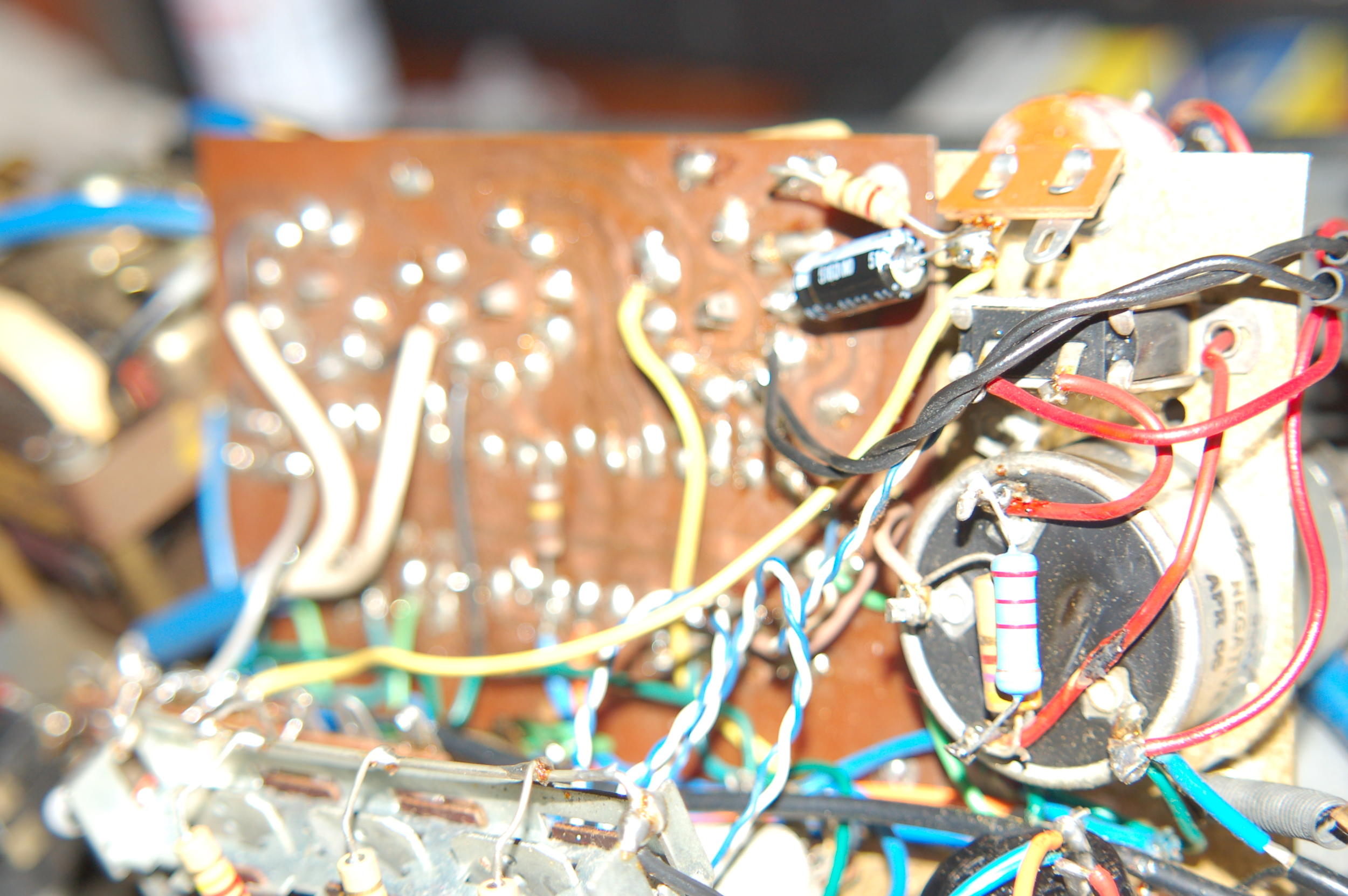
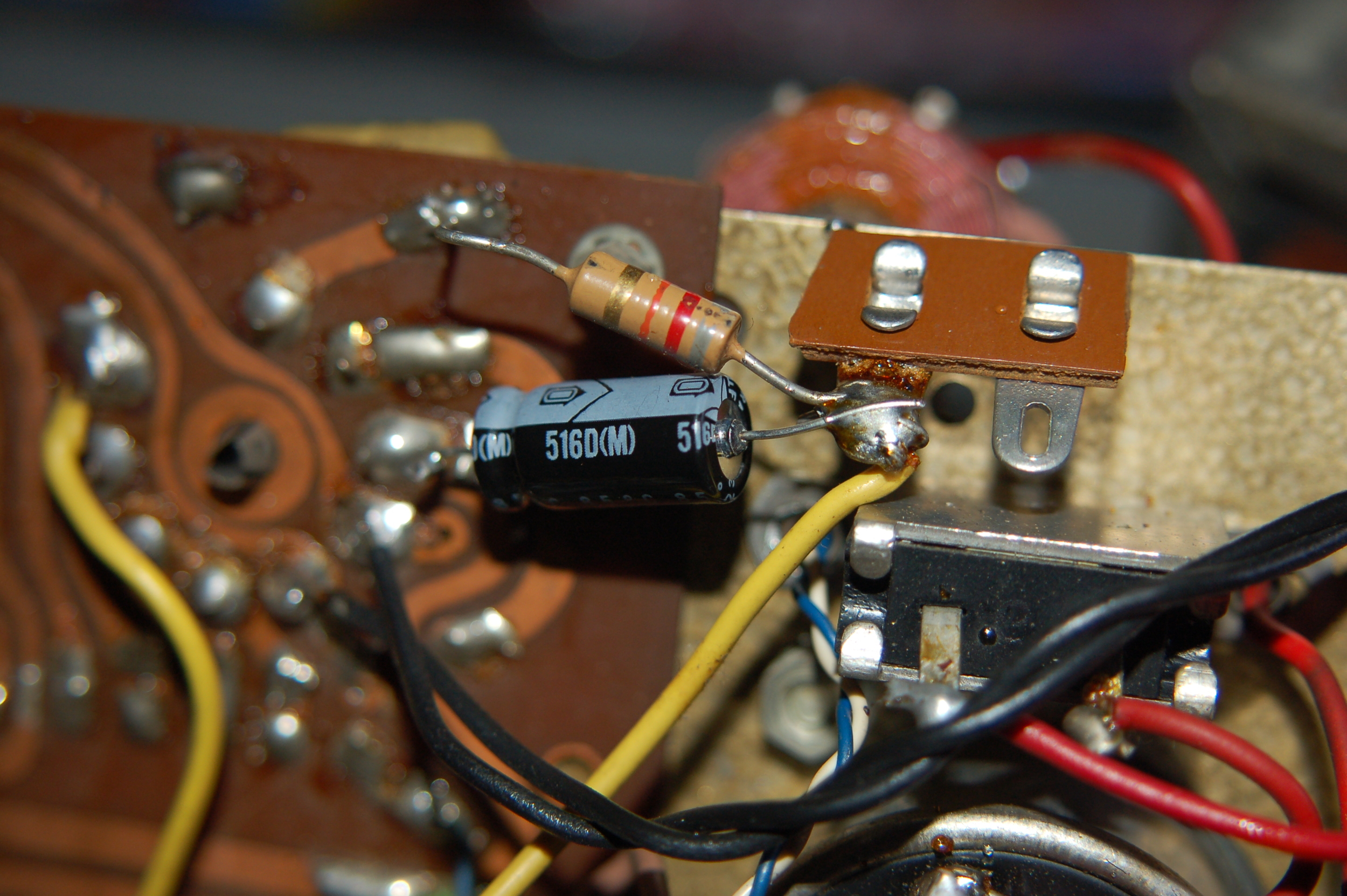
Other issues: As you can see here this resistor is also overheating, to such a degree that its coating is coming off and it has also melted through the sleeve of the wiring behind it. Time to break out the Multi-meter and schematic then...

Here we can see the schematic of the Valve Copicat with diagrammatical references of the parts I have replaced.
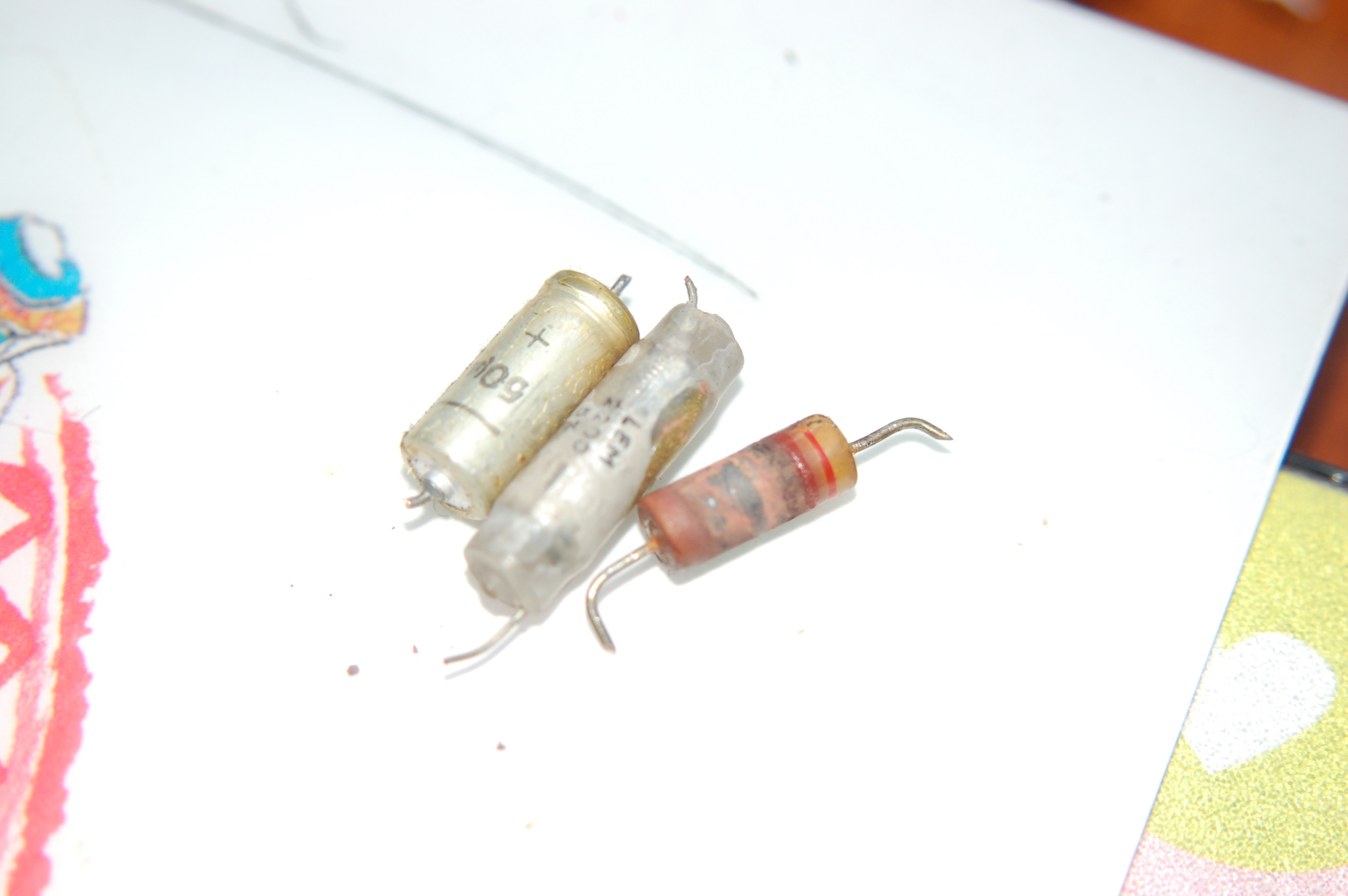
- A = The melted polystyrene capacitor on top of the oscillator coil. This was replaced with a Philips 1% Polystyrene Capacitor 650V
- B = The overheating resistor, 2k2ohm 5Watt. "Caution! These Capacitors can store a lot of power and shock you badly, be careful!"
- C = An electrolytic capacitor which determines gain of the stage, measured at 70uF, should be 50uF (probably this part has dried up over time causing a drift in capacitance value)
- D and E = Electrolytic capacitors that I have earmarked for replacement when...well...when I can be bothered. (They're hard to get to without removing the PCB which frankly I can not be bothered to do right now)
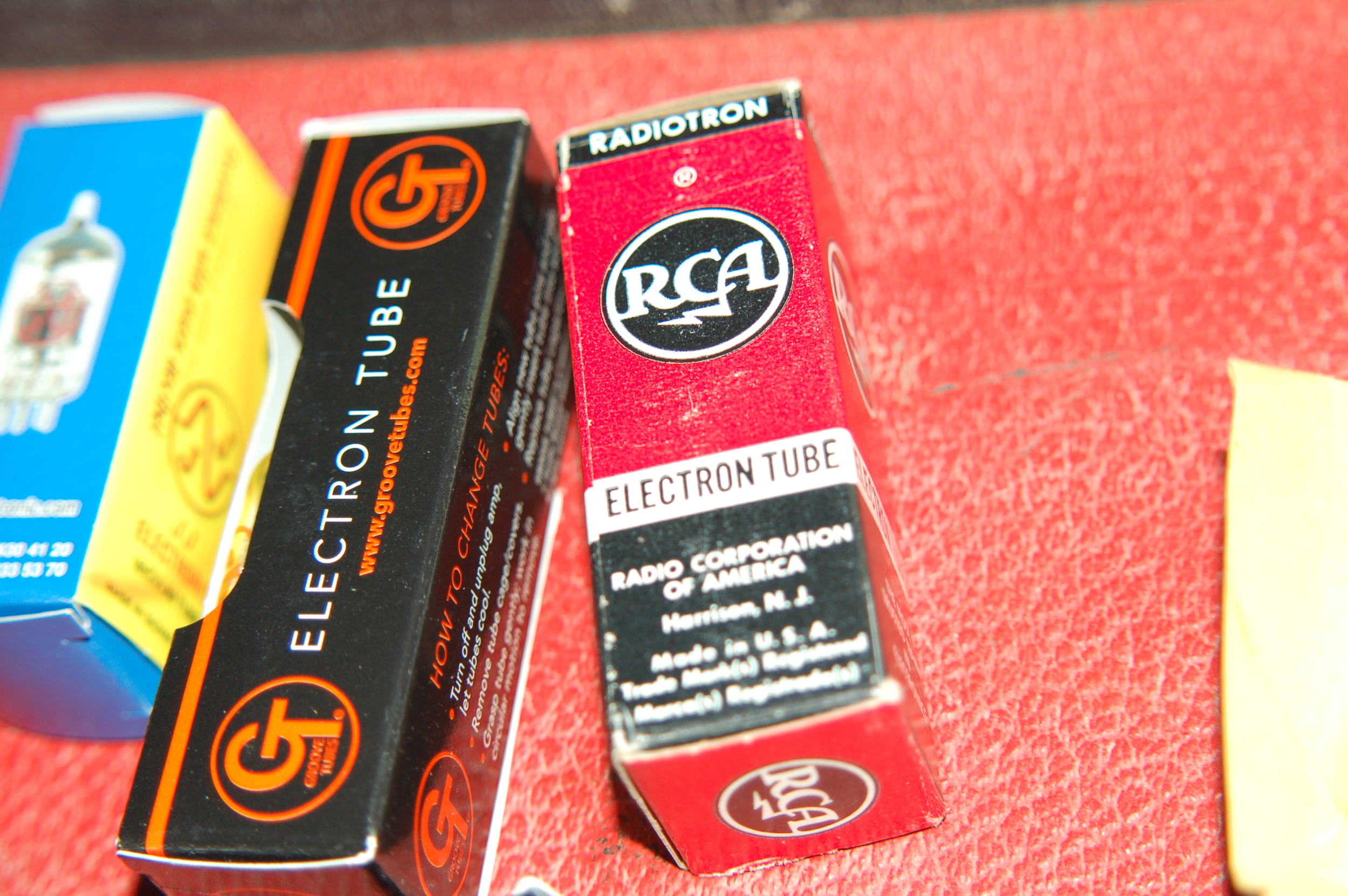
After soldering in the new parts and popping in some modern Valves the thing fired right up and sounds fantastic. I'm just glad I didn't electrocute myself with 230 volts, not nice, believe me I know.
So... until next time.