Project Überdeck, Status: Complete
Introduction
For a long time now I have been concerned with standing away from the traditional production, performance and DJ tools/aesthetic, focusing instead on creating my own custom devices to suit my own needs. In my opinion; in order to create original work you need original tools and/or original working methods.
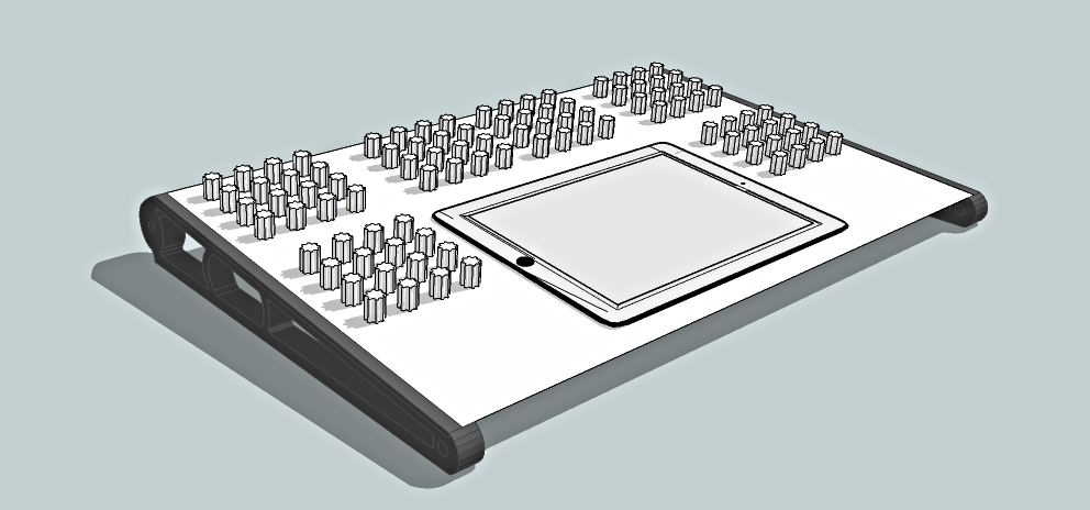
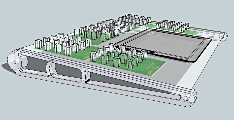
Recently I decided to design my own performance interface combining the best, to my eyes, of hardware and software to allow expressive control without tactile limitation associated with traditional "point-click" methods of interacting with Music software. Seen depicted diagrammatically above is the initial rendering of this basic concept; hereinafter referred to as Überdeck.
The Concept
Inspired by the works of Ableton Legend; Robert Henke (et al.) and his custom Abelton controller Monodeck II and the 'Henke inspired' Protodeck of Jullian Bayle, aka Protofuse; Uberdeck combines physical MIDI rotary controllers with clip launching/event triggering functionality.
In both Henke's, and in Bayle's development that followed, the designers chose to combine physical hardware buttons for triggering of events (of the momentary push type) with multicolour Light Emitting Diodes (LED's) in order to give the user visual feedback as to the operating states of the individual clips/events that are being triggered in real time. For some I had pondered the same approach and even designed and prototyped a PCB to that end, however, after some further thought it appeared more logical to me to implement the iPad vs custom buttons for various reasons.
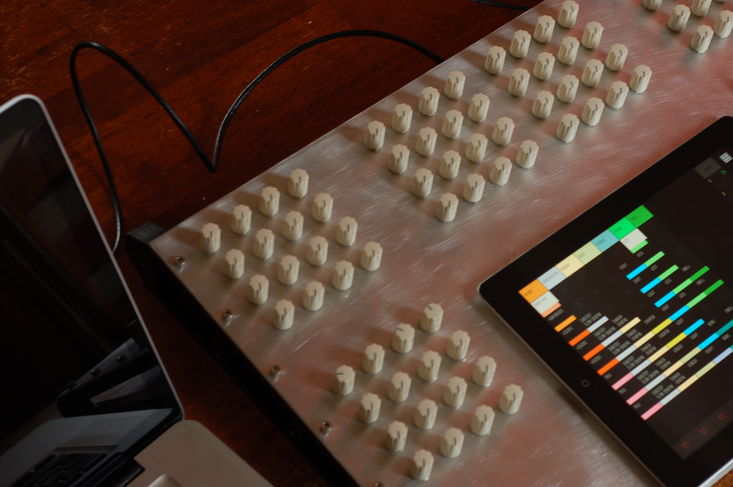
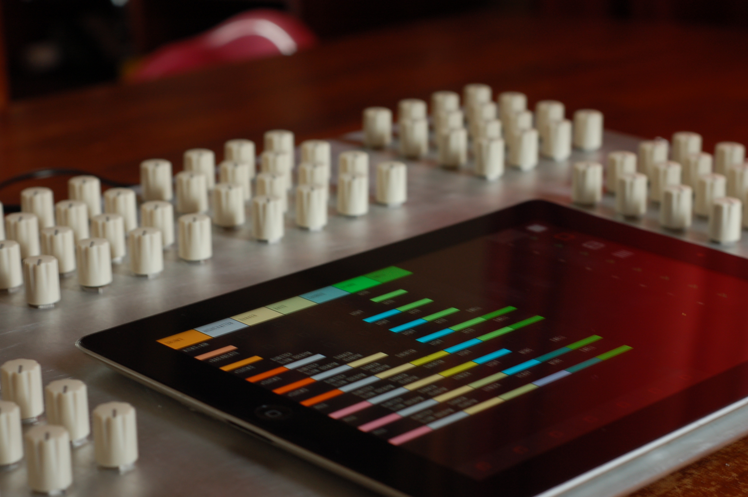
In recent times there have been many great developments for iPad users in term of expressive musical/performance control interfaces. Most notably Jazzmutant's Lemur a multitouch device of standalone nature which has since been released in iPad format by the good folk over a Liine but also including Traktor DJ, mrmr, touchOSC and my recent favourite Conductr. In my opinion however the iPad (other touch capable devices are available) is limited in one respect: attempting to perform linear and rotary motions on a touch screen is a cumbersome process and prone to error in use as the finger(s) slip.
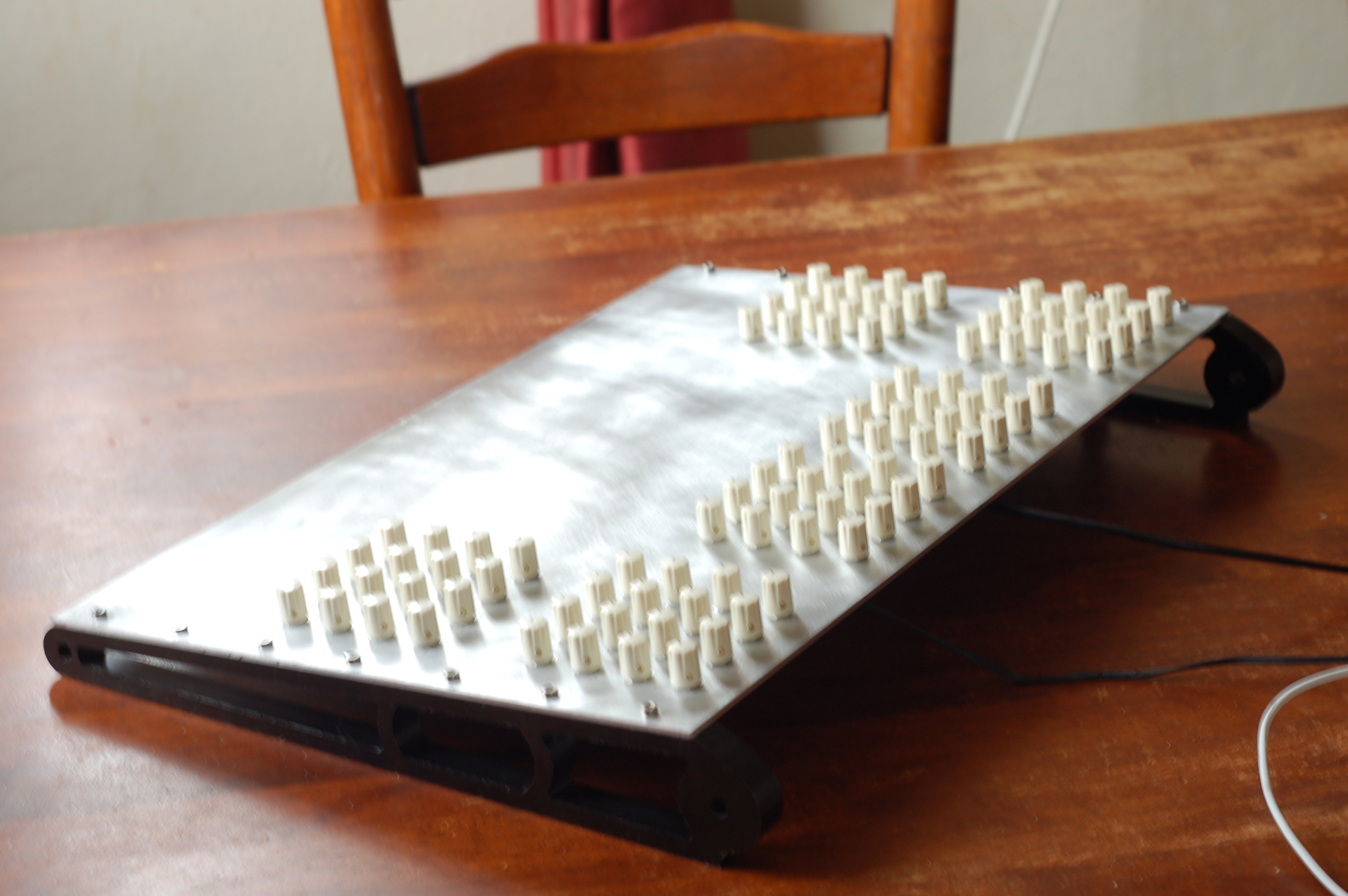
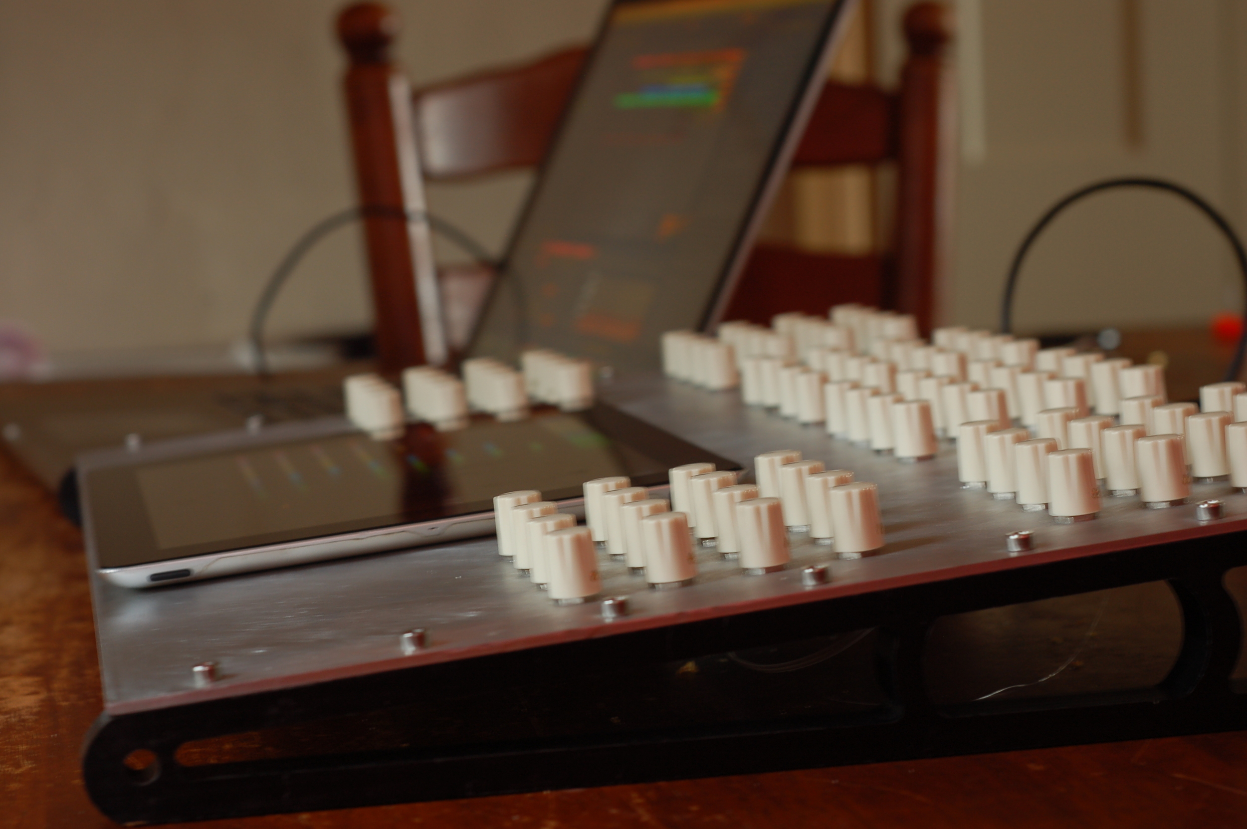
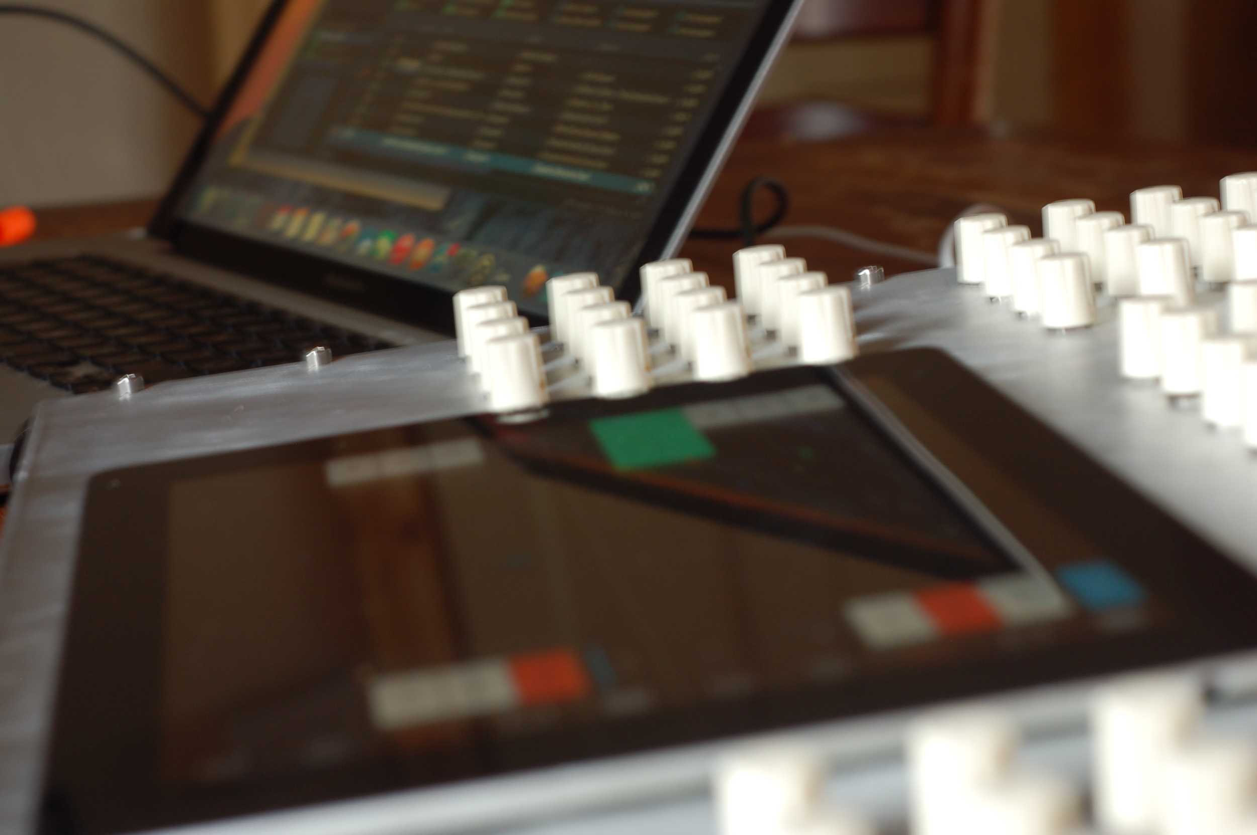
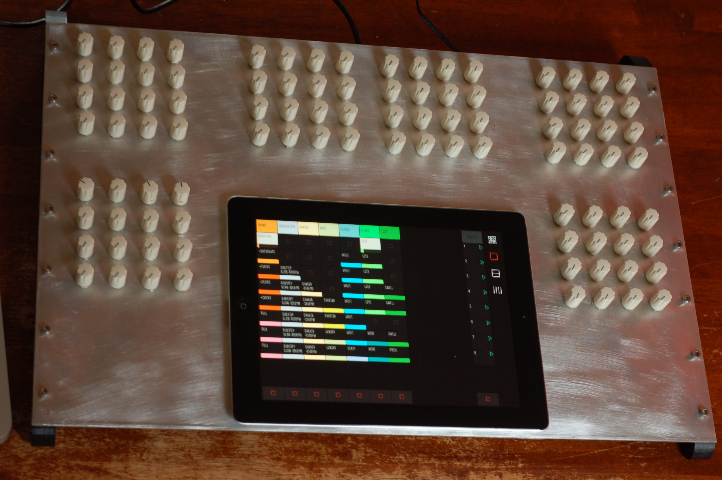
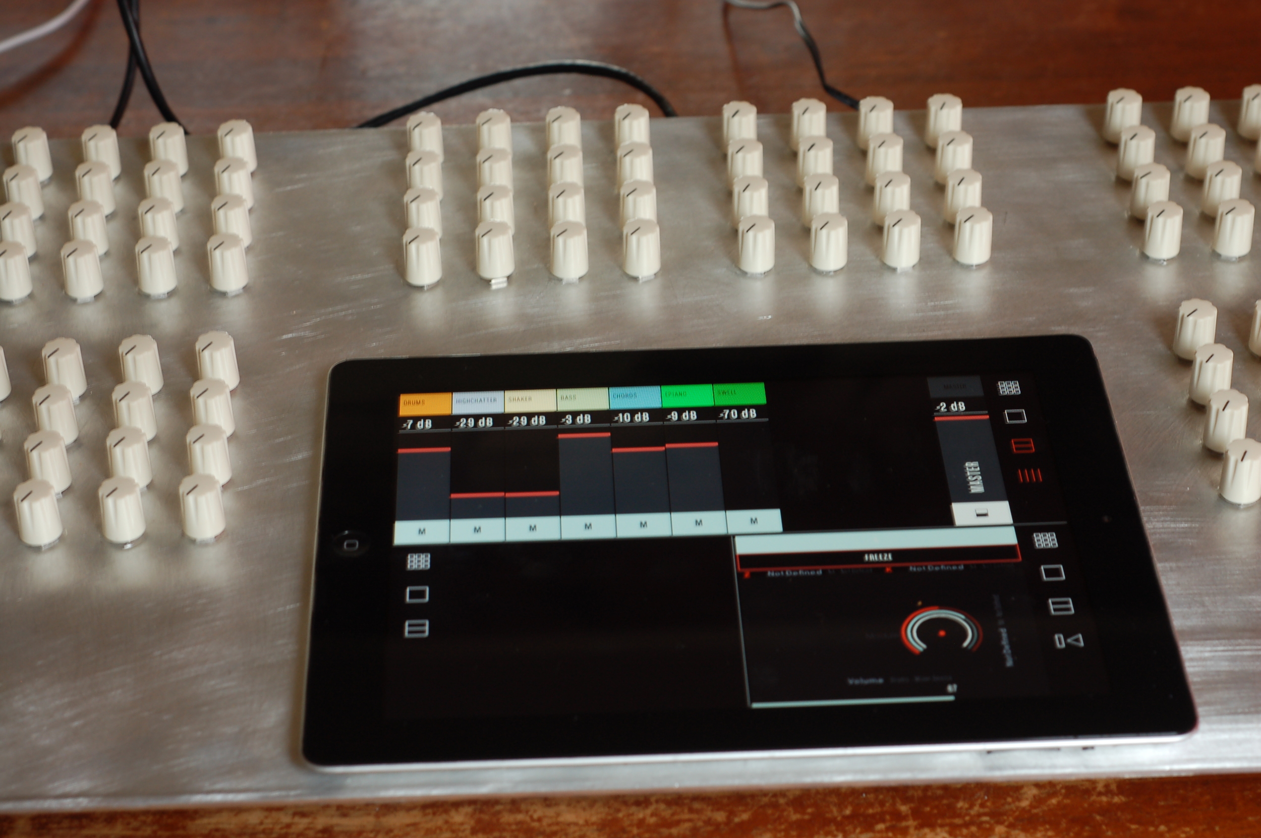
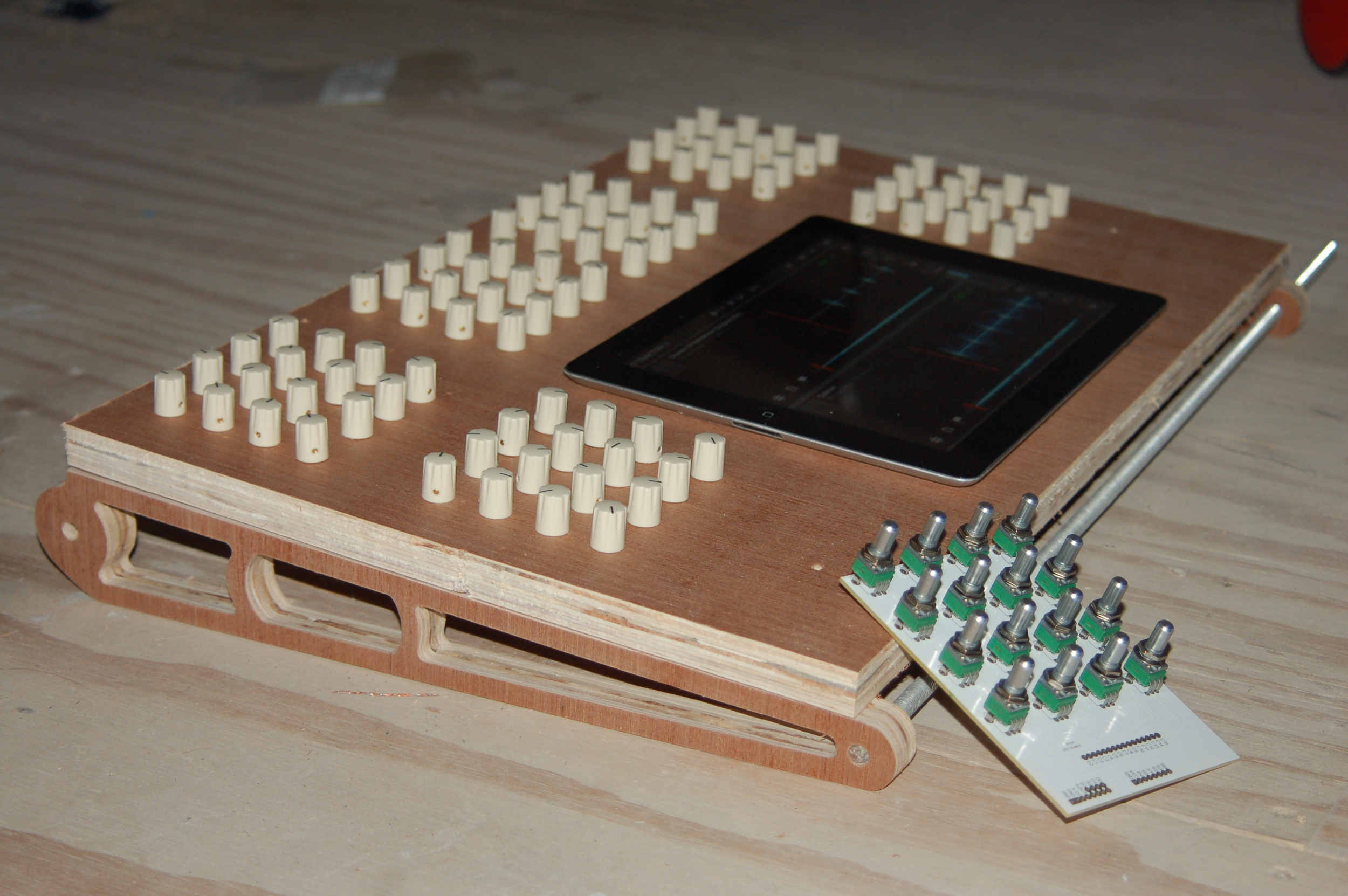
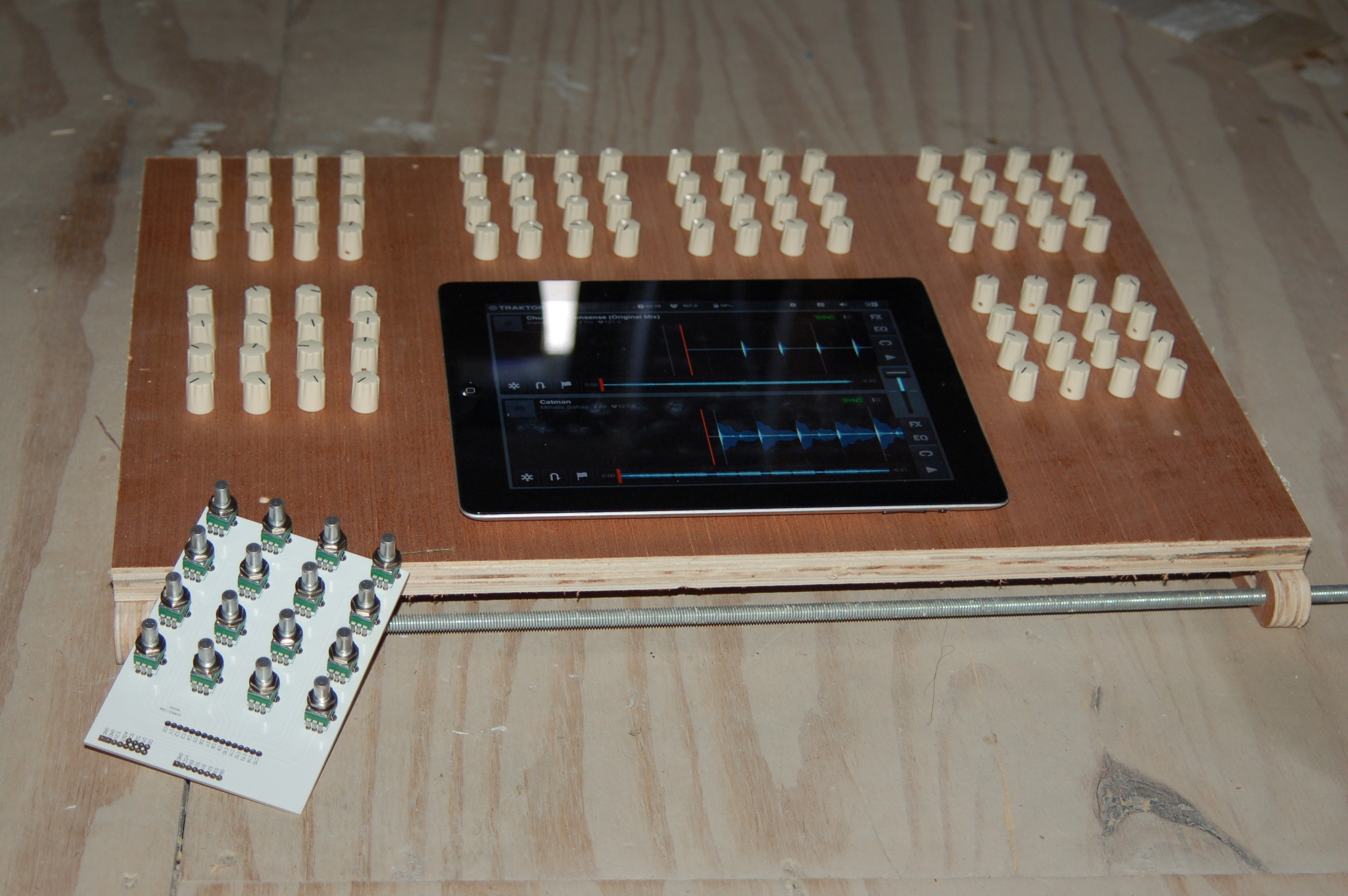
This development then is aimed to primarily combine the best of the both worlds as I see it; the accurate and tactile rotary motion provided by physical rotary controls, with the extensive visual feedback and triggering functionality provided by a touch screen. Not to mention the scope to design custom triggering interfaces using apps such as the aforementioned Lemur, TouchOSC and mrmr.
Specifications
- 96 Rotary Potentiometers (High Quality PCB mount vertical) producing MIDI Control Change (CC) messages on a single channel.
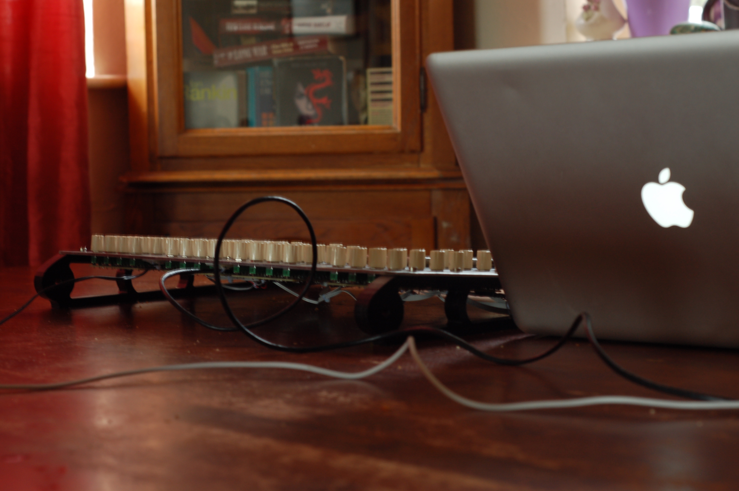
- Standard USB MIDI protocol (no driver required, non reliant on Max4Live)
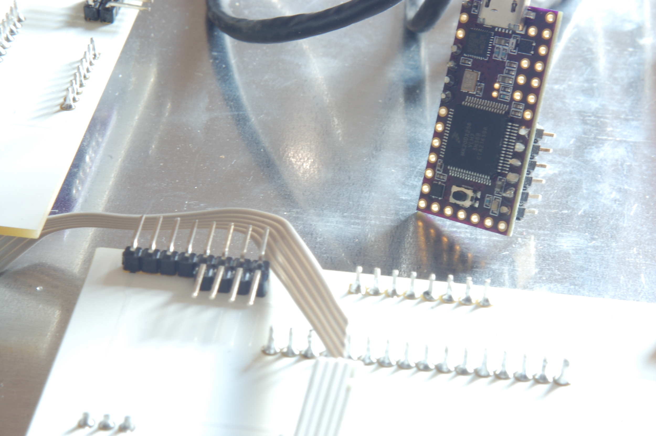
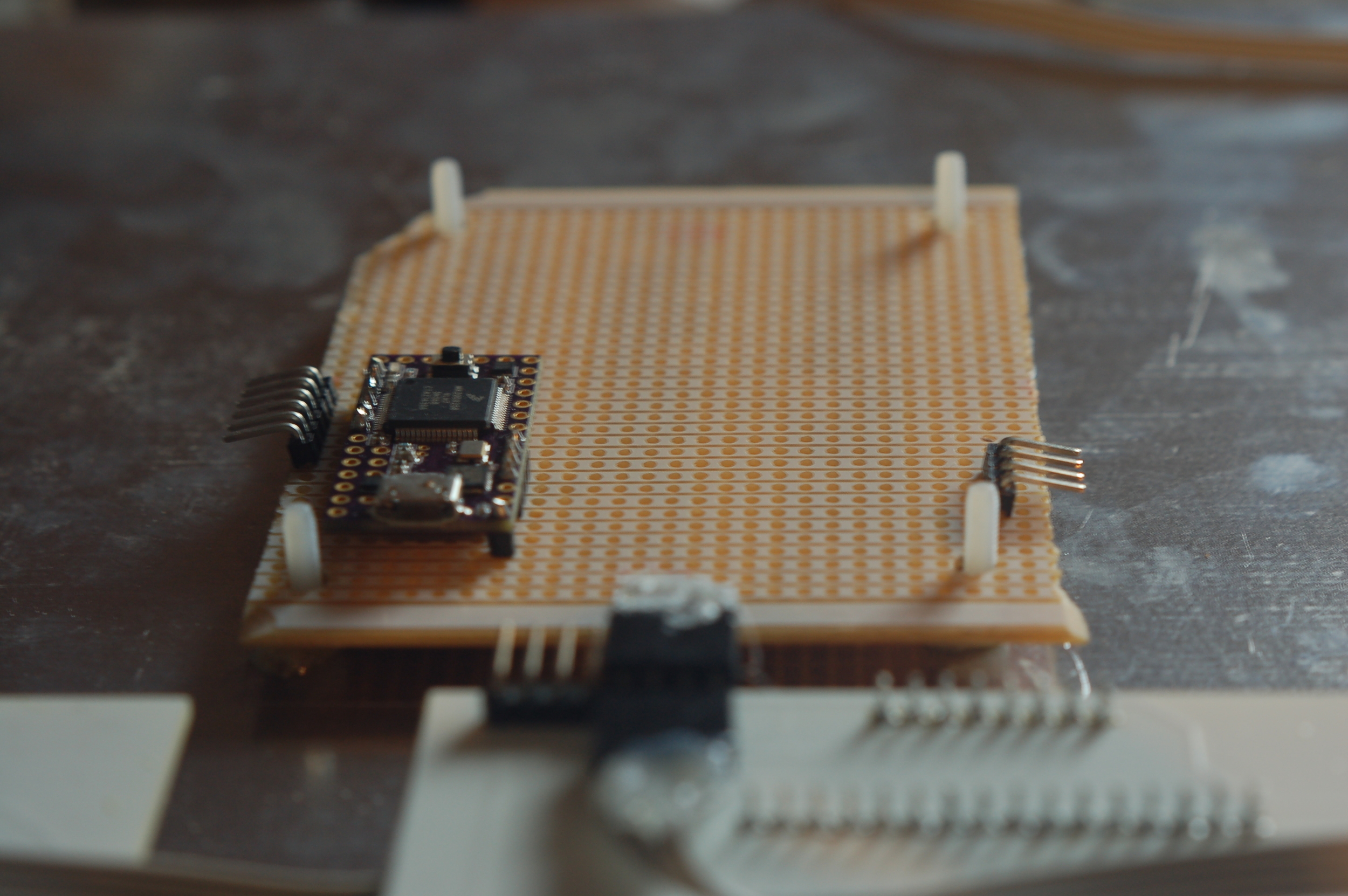
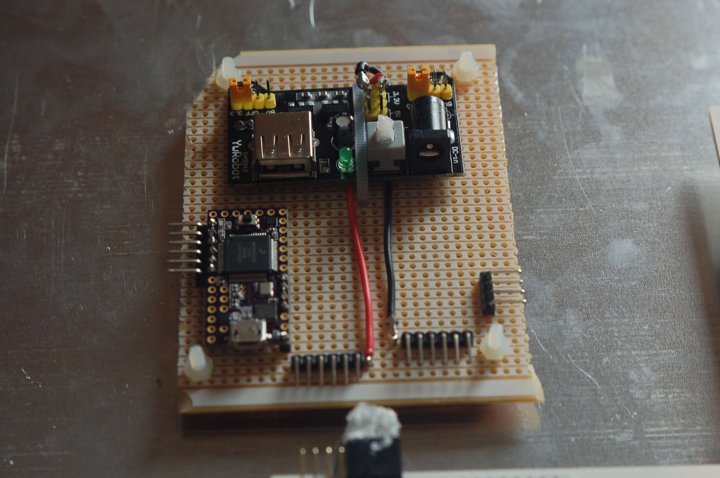
- Powered by Teensy 3.1
3D Design
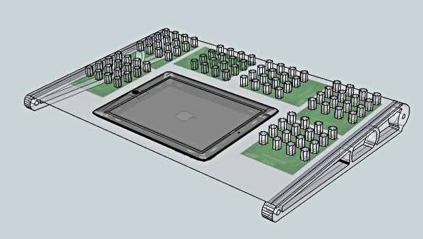
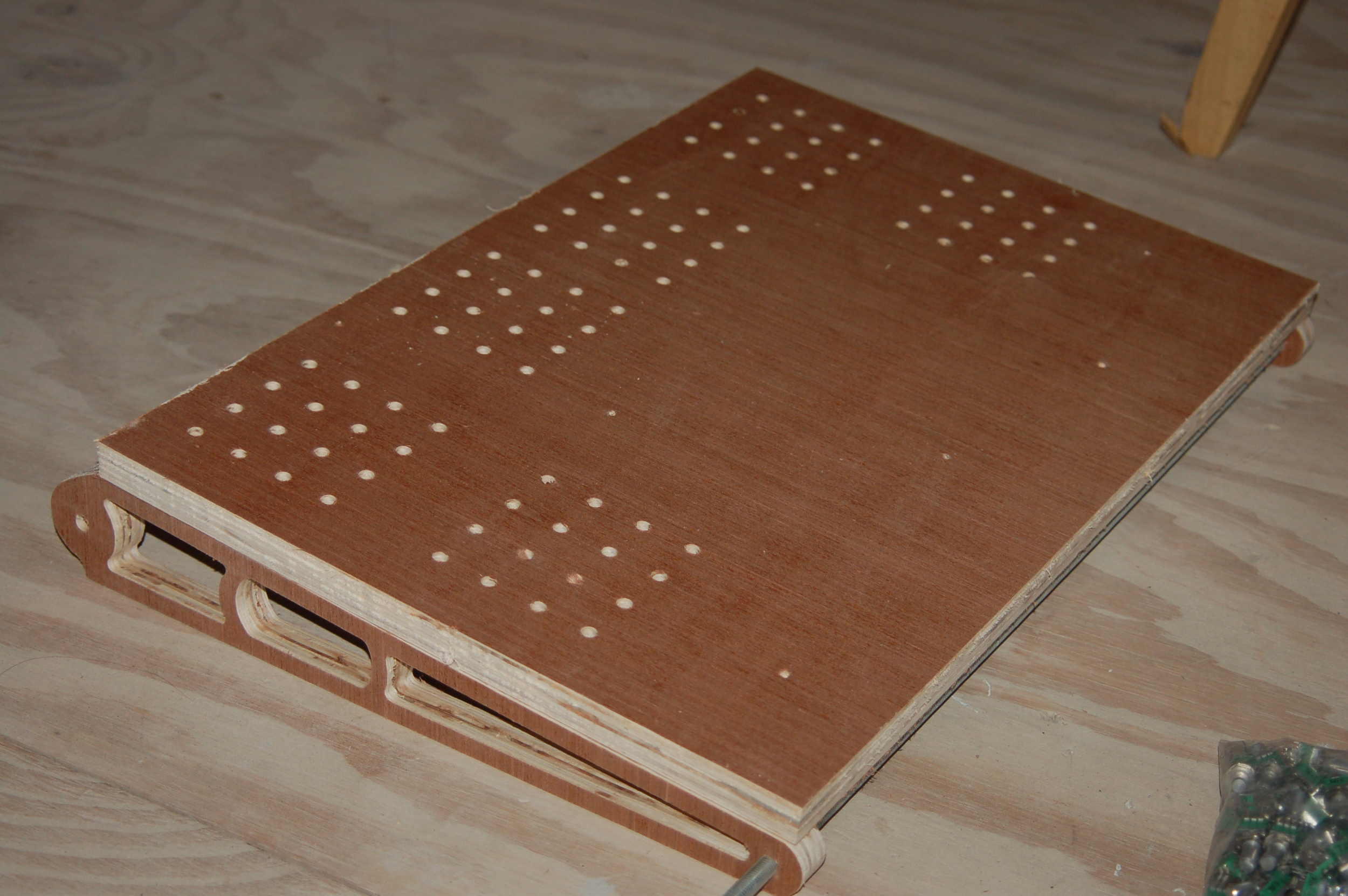
The first process of this project was the completion of a 3D model, from which the relative elements could be milled on CNC, more detail later. This process really has to happen alongside the development of the circuitry and whilst I had some idea of the overall design it was important to begin from a low level to ensure that things would fit together as they should. This means beginning by sourcing the components to use and building the design up from there. Below we can see some of the early renderings which were modelled around the PCB design and the all important central iPad.
Circuit Design and Considerations
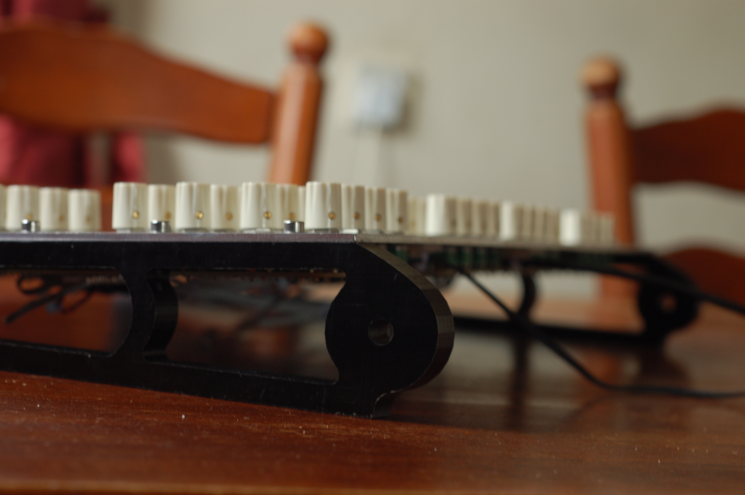
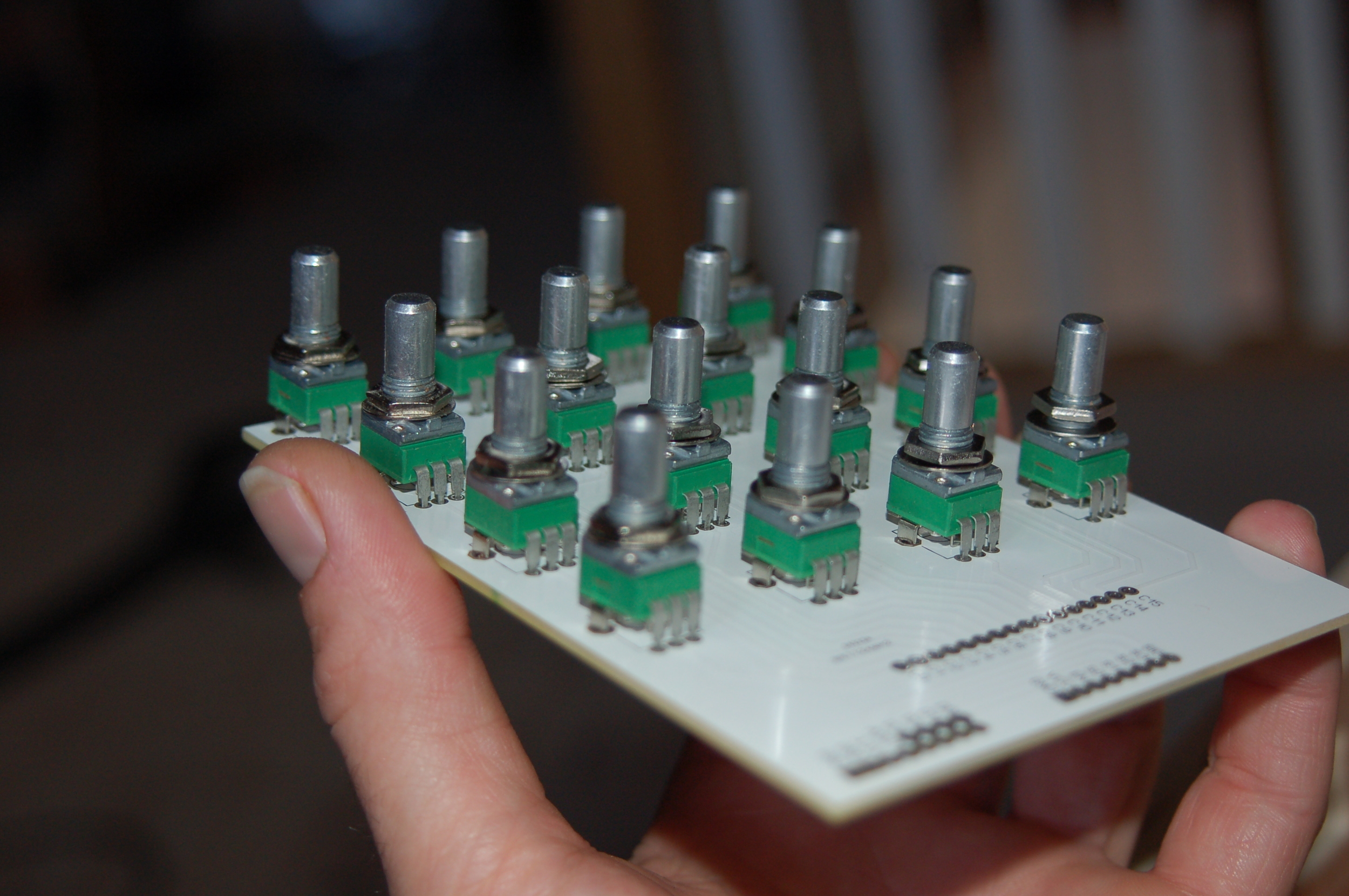
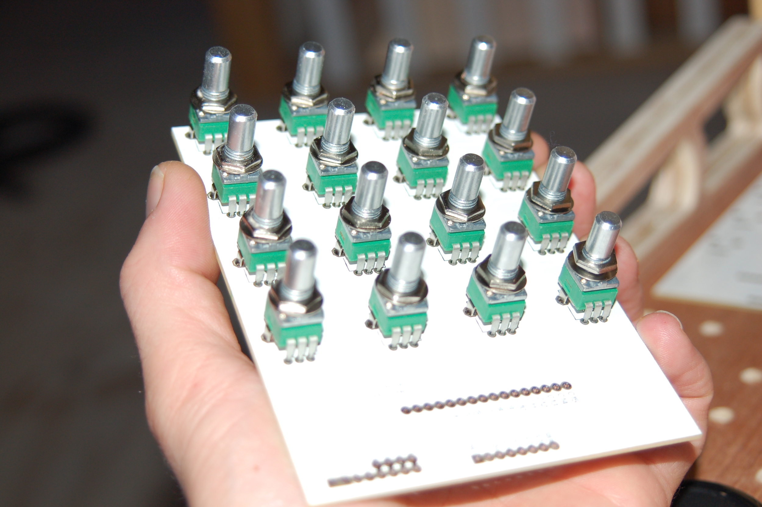
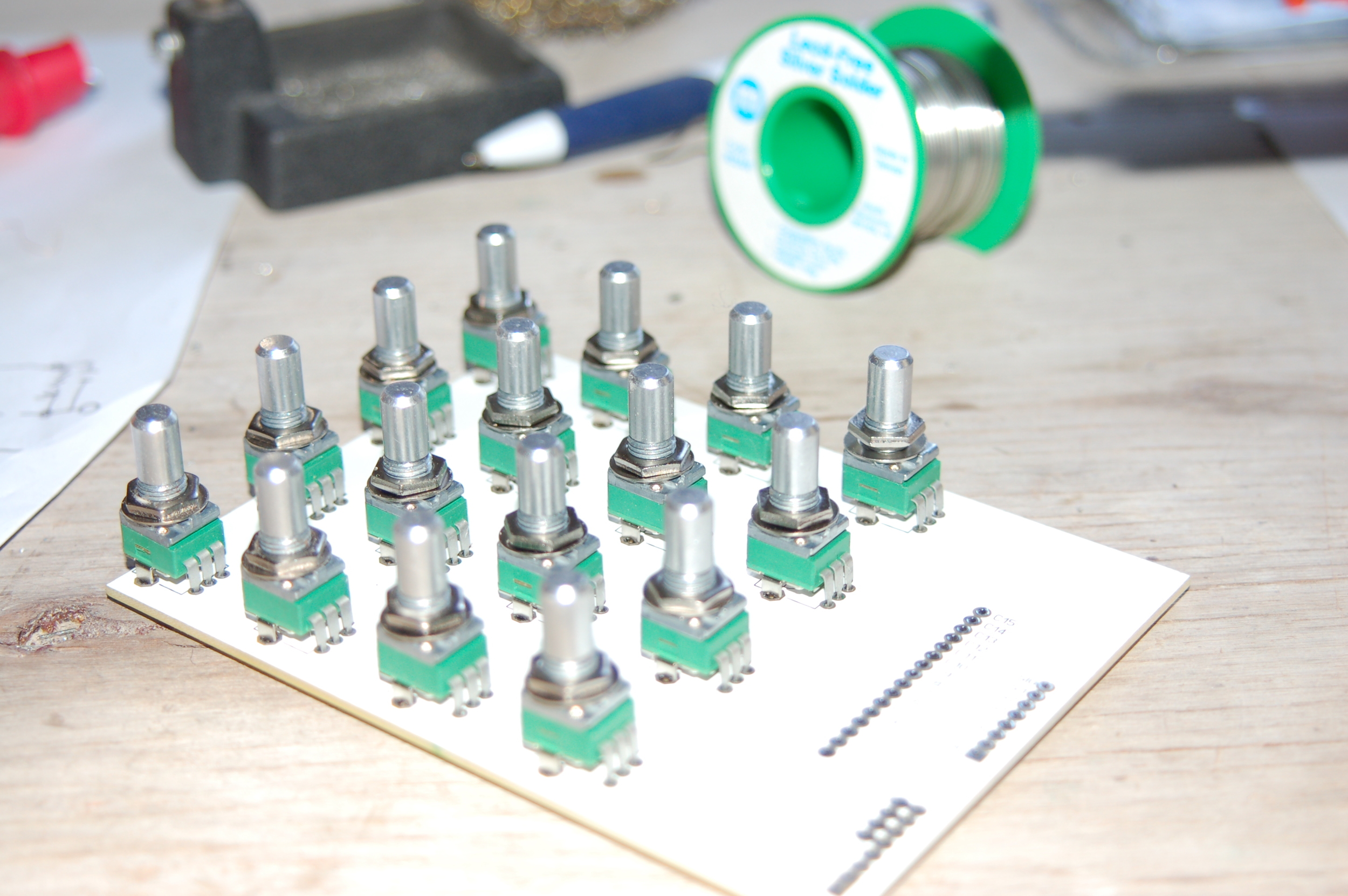
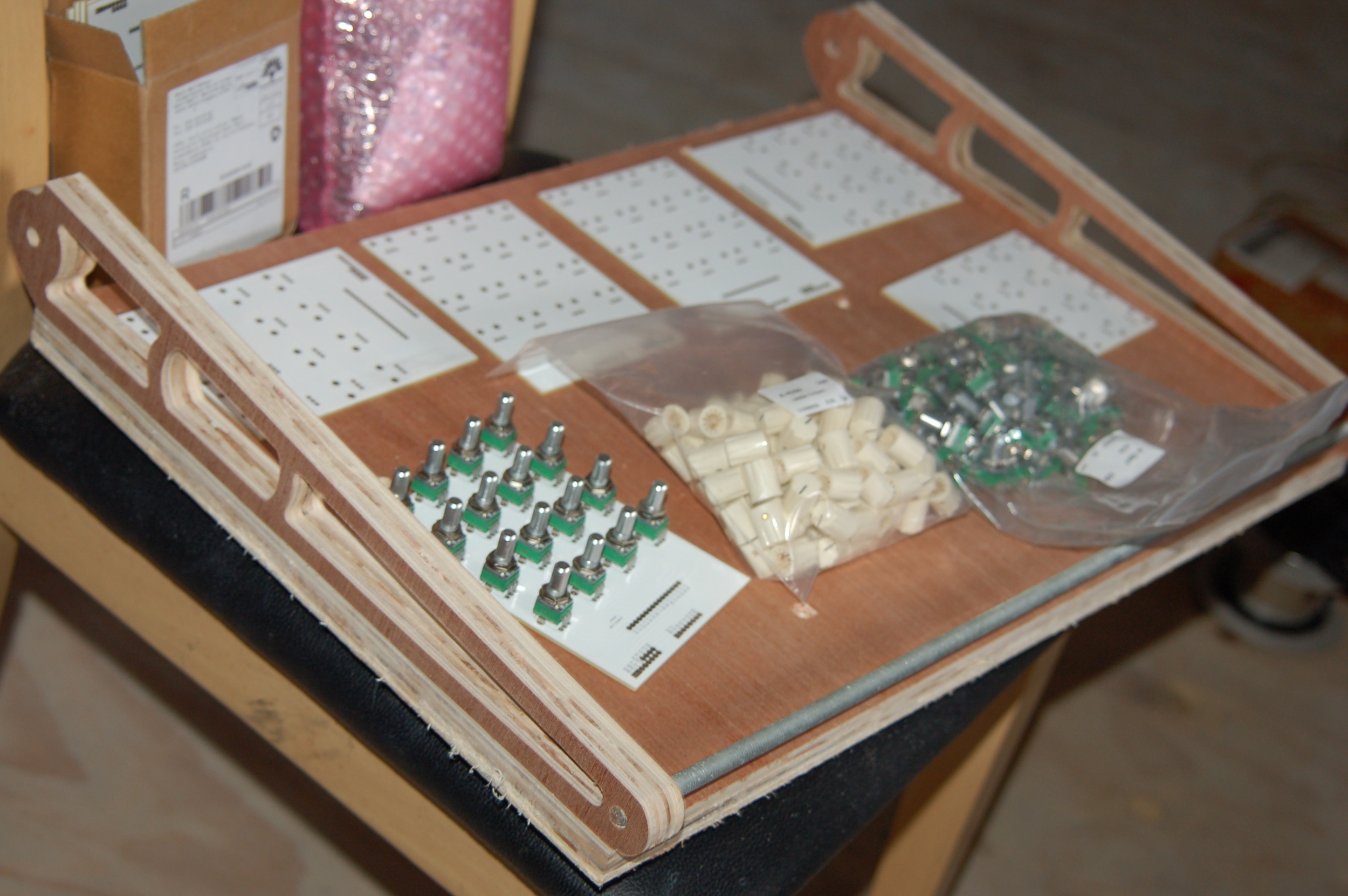
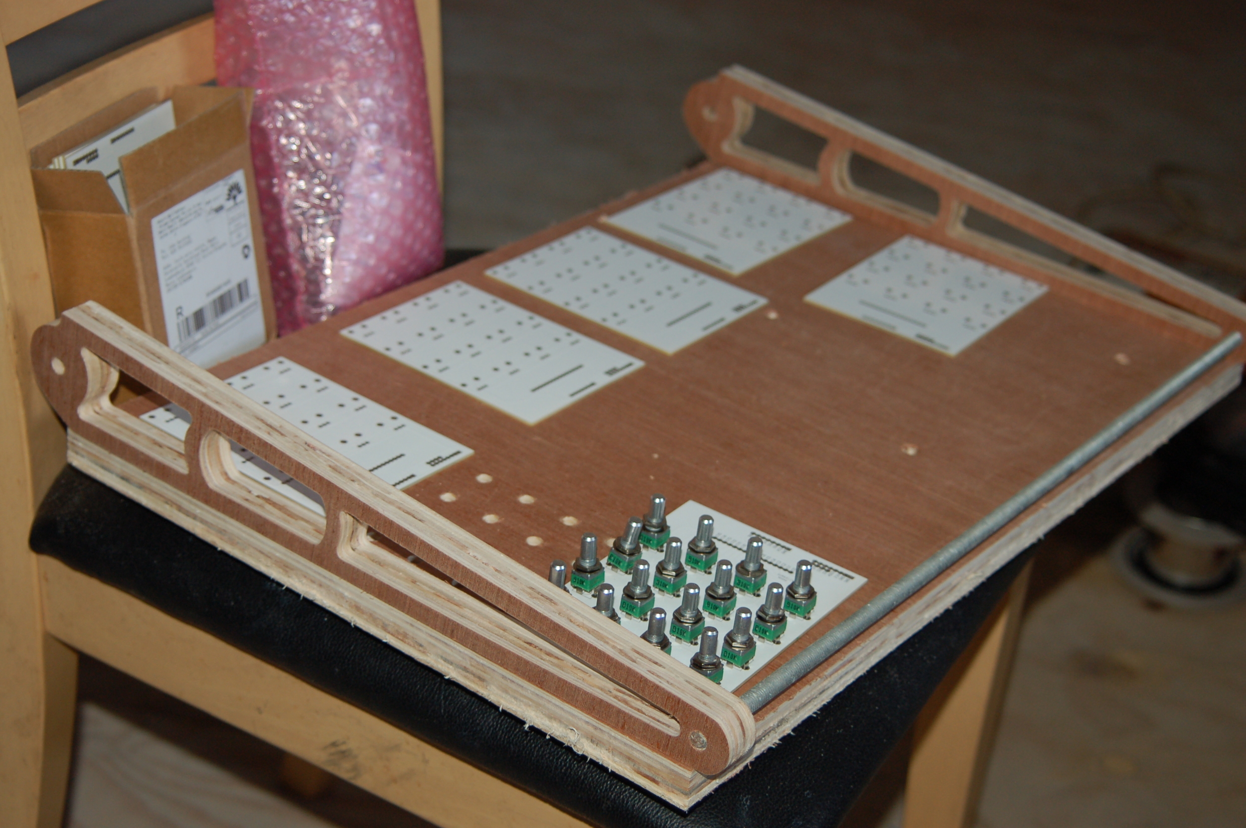
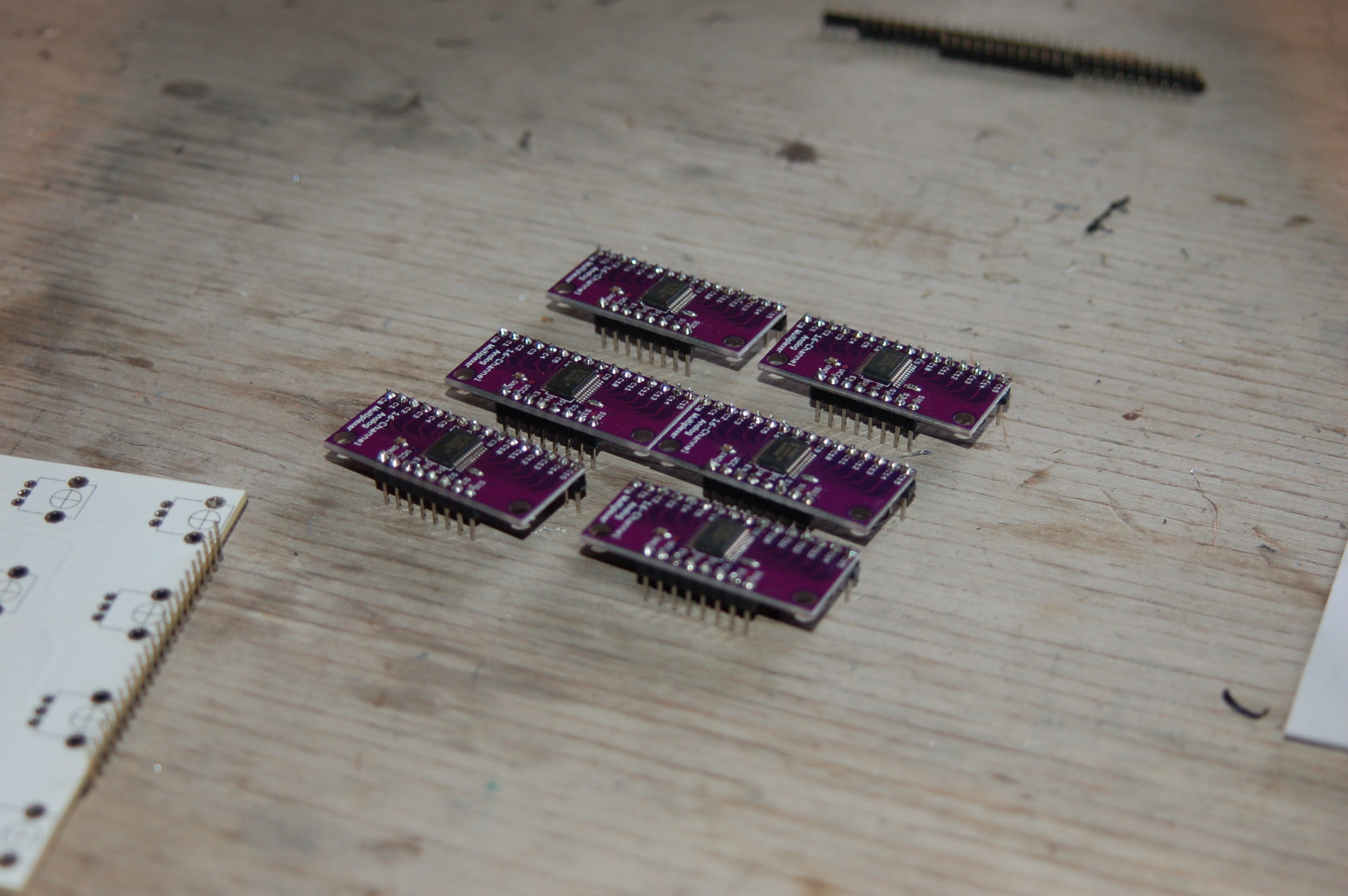
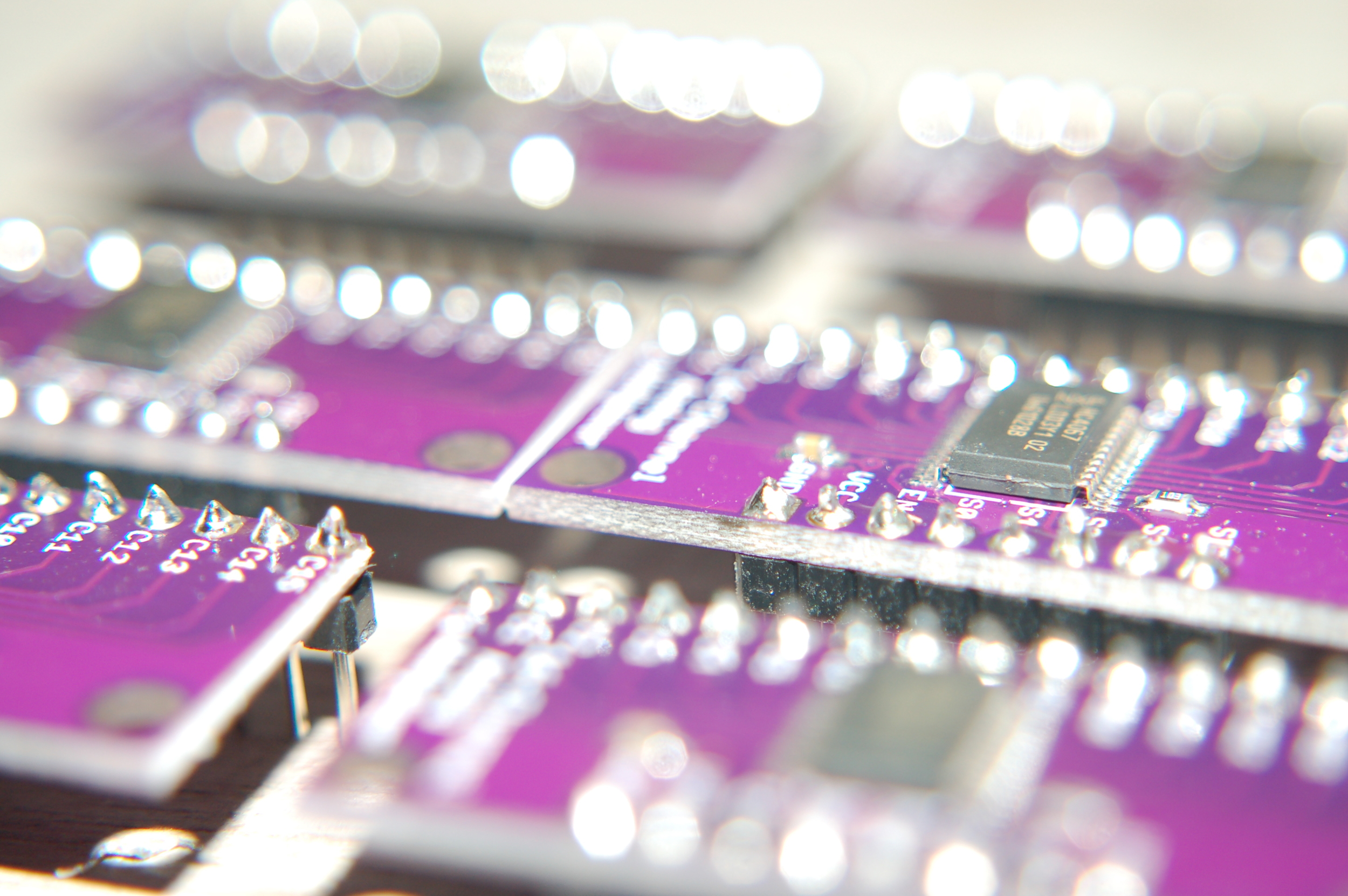
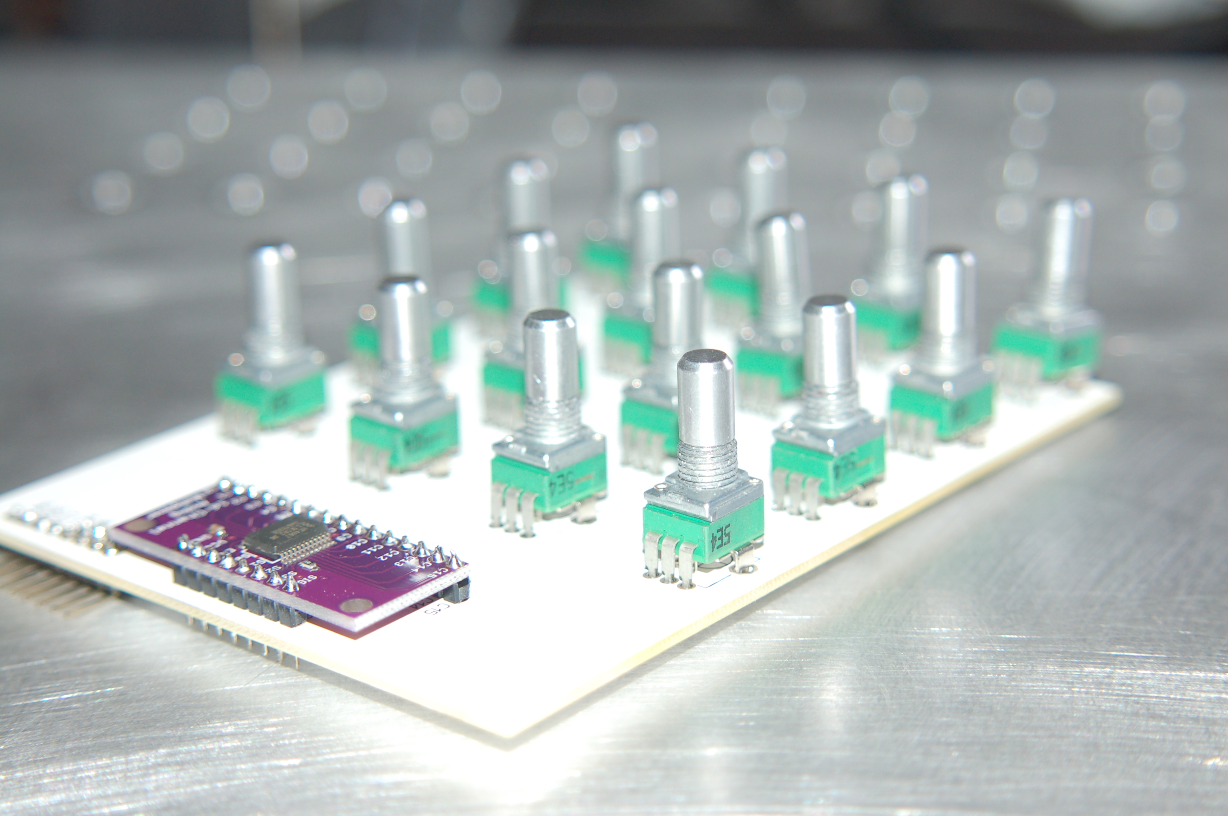
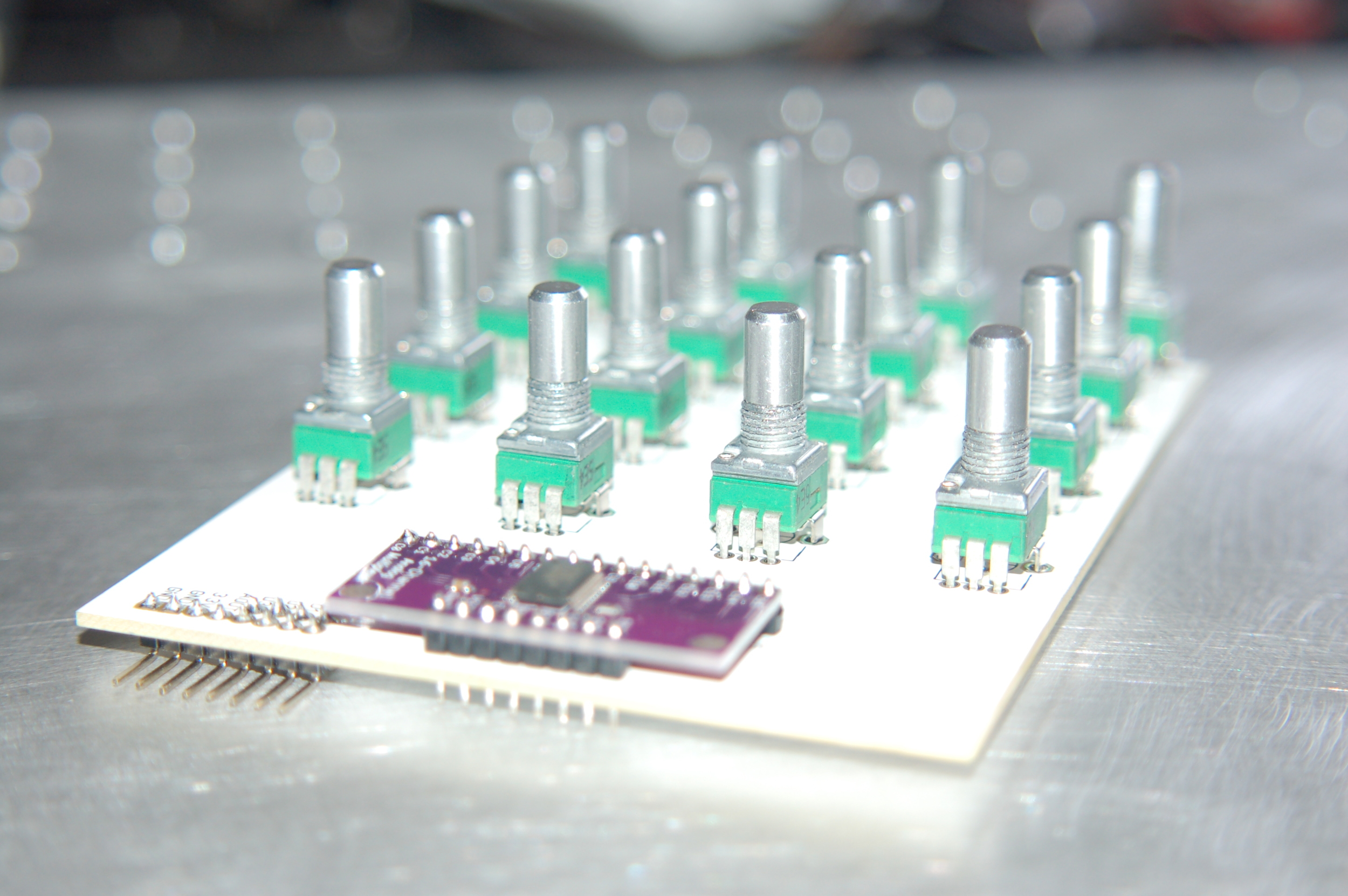
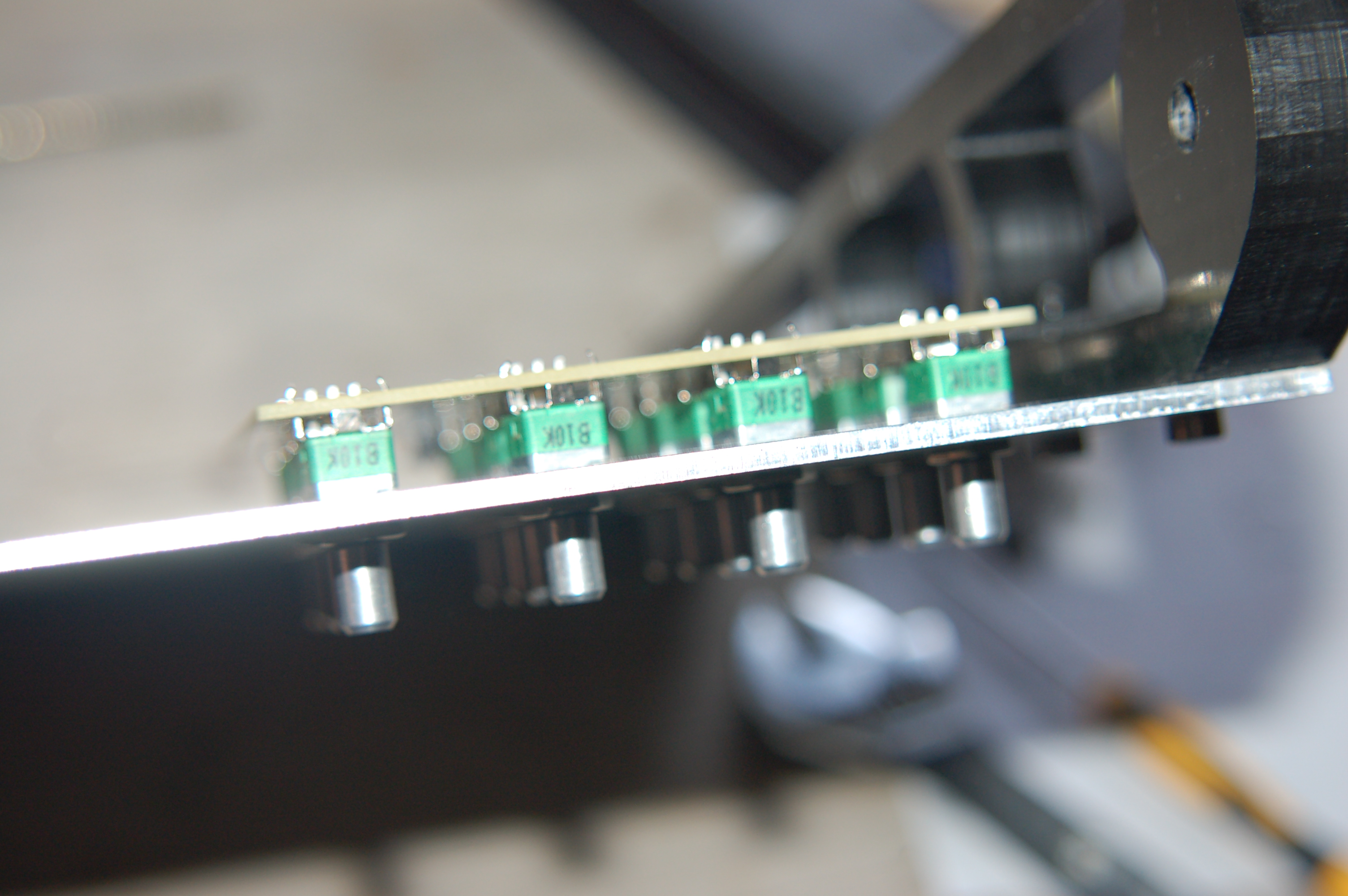
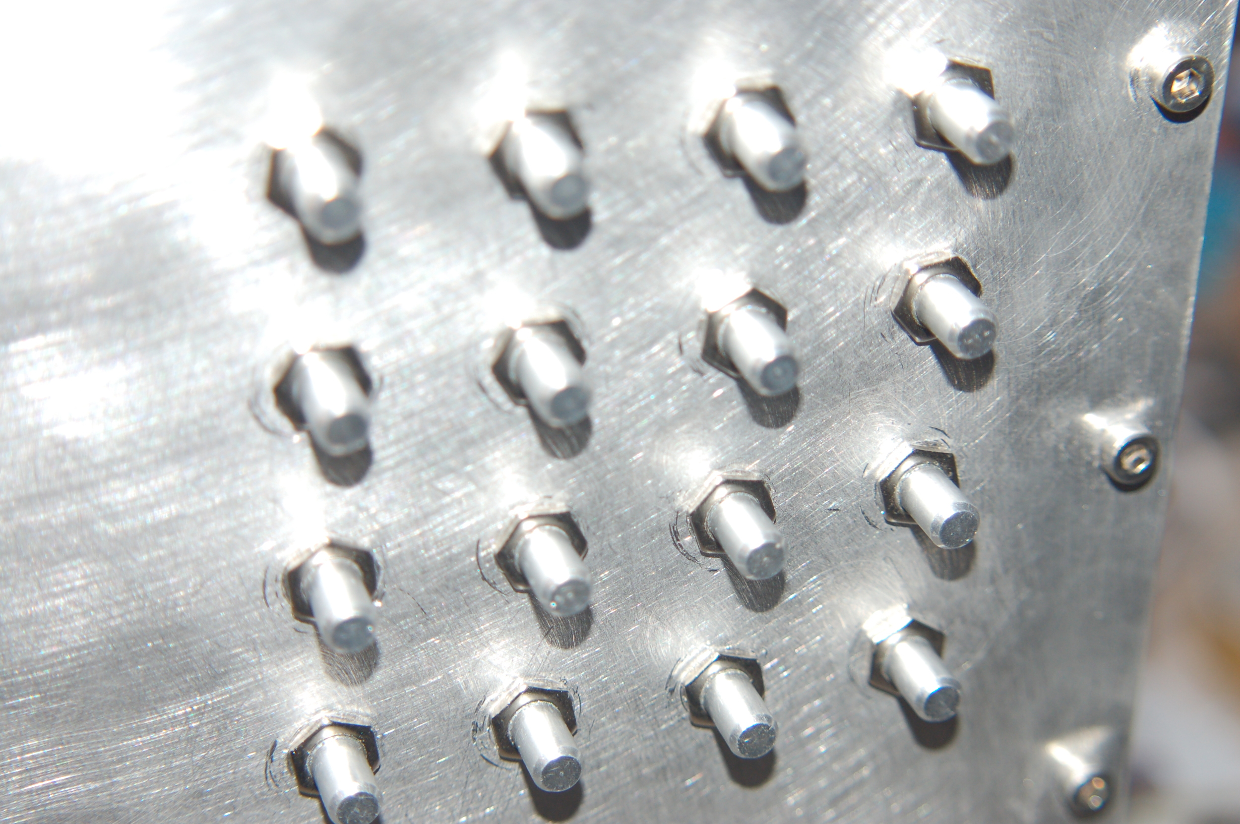
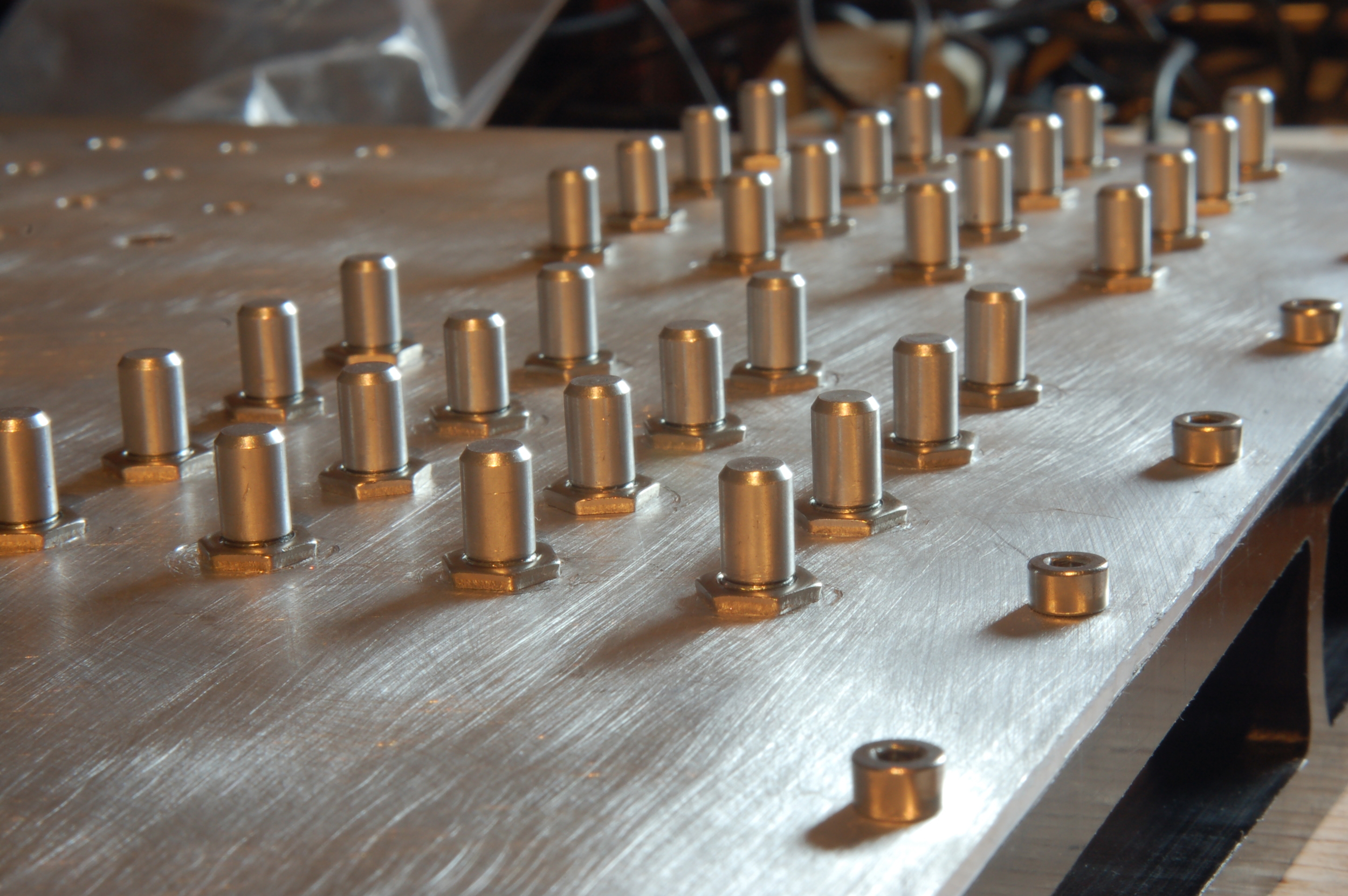
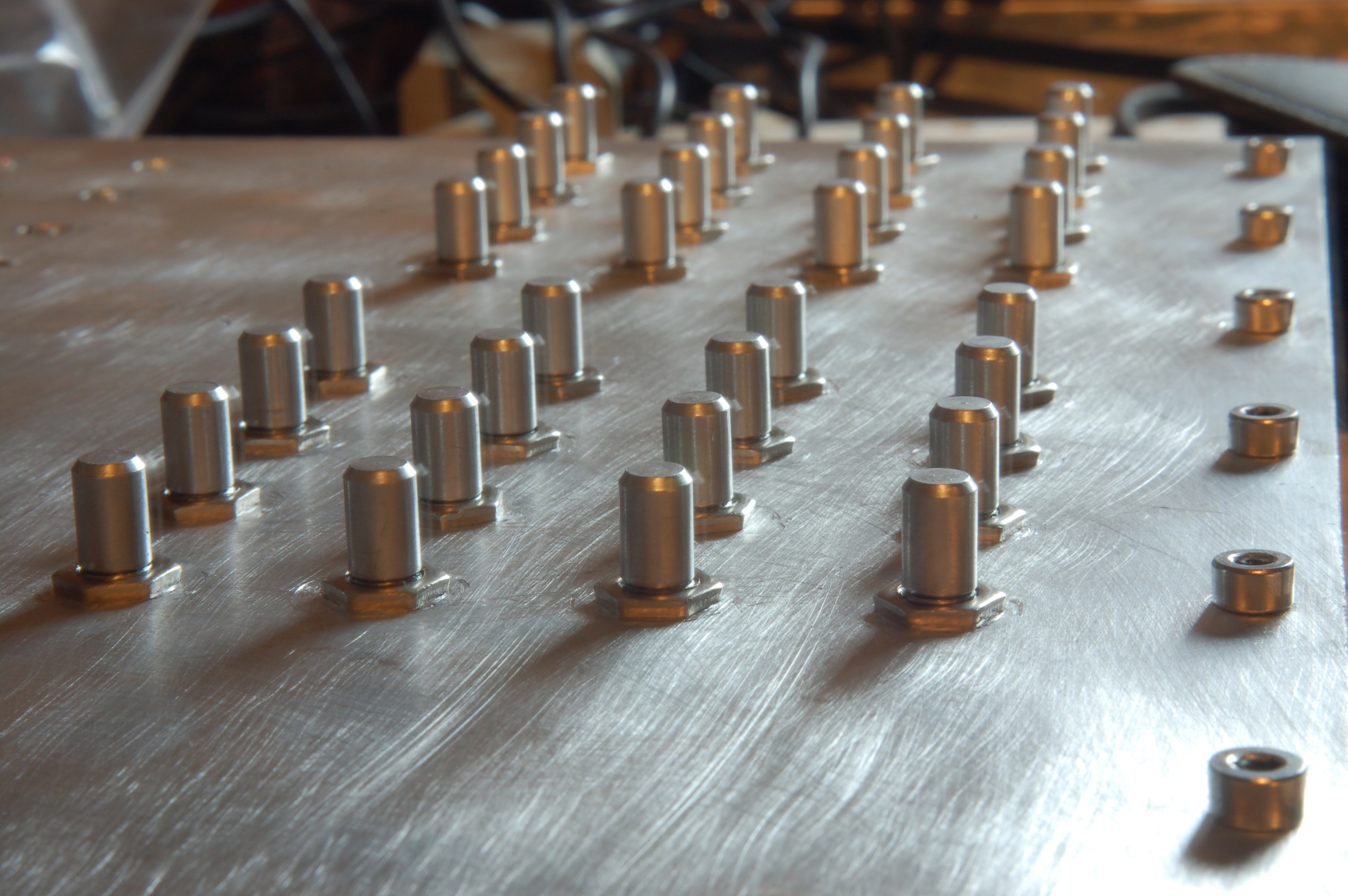
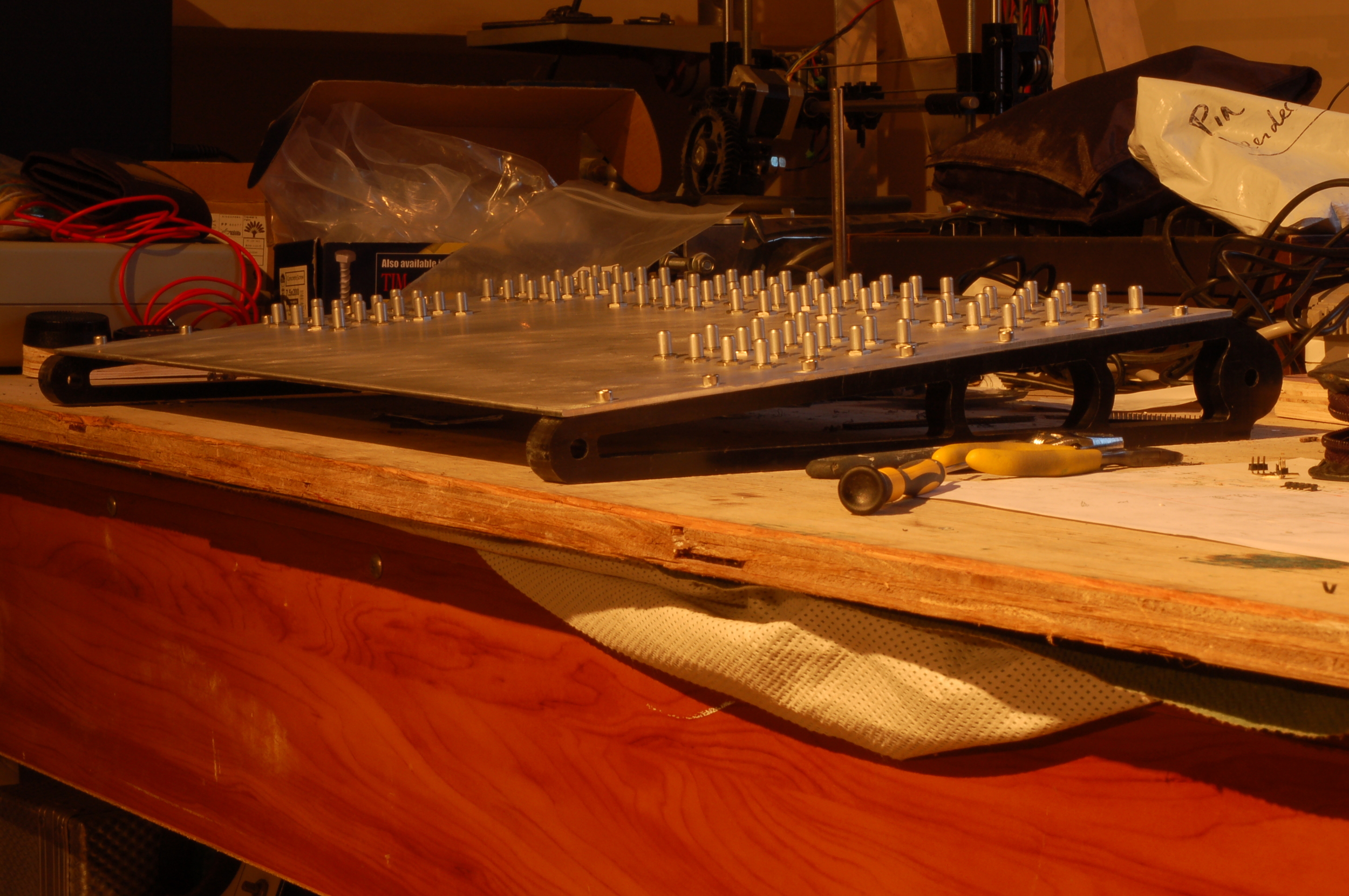
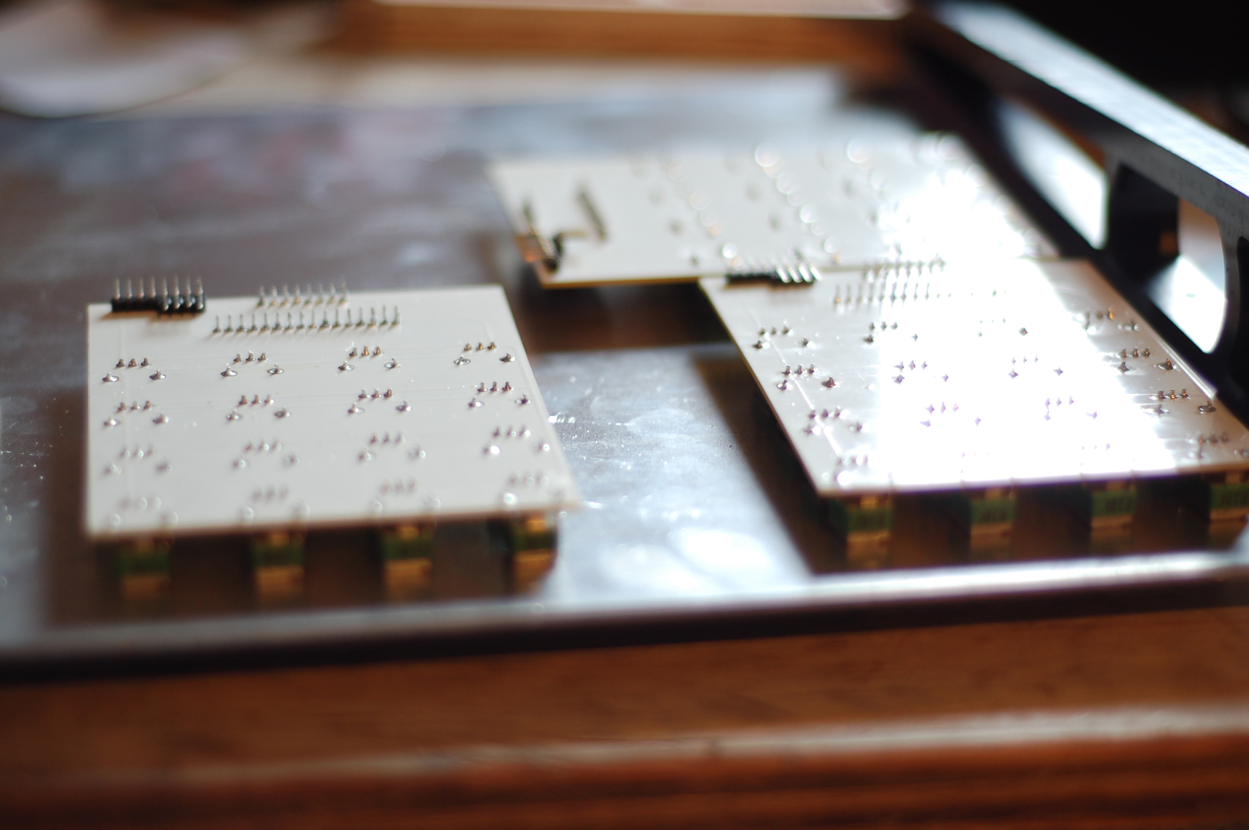
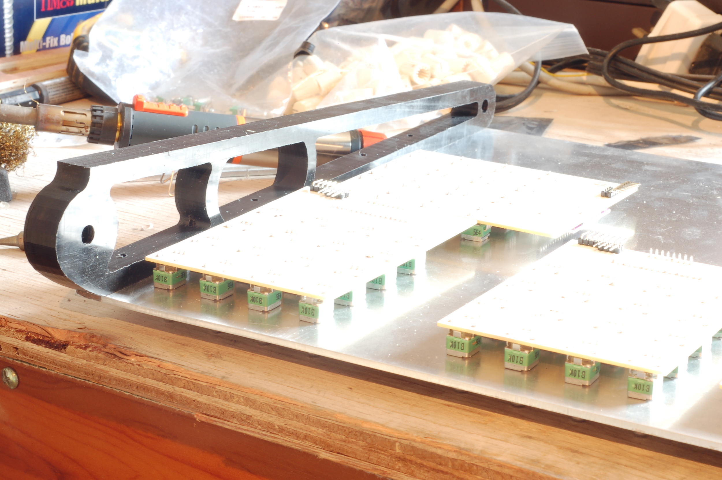
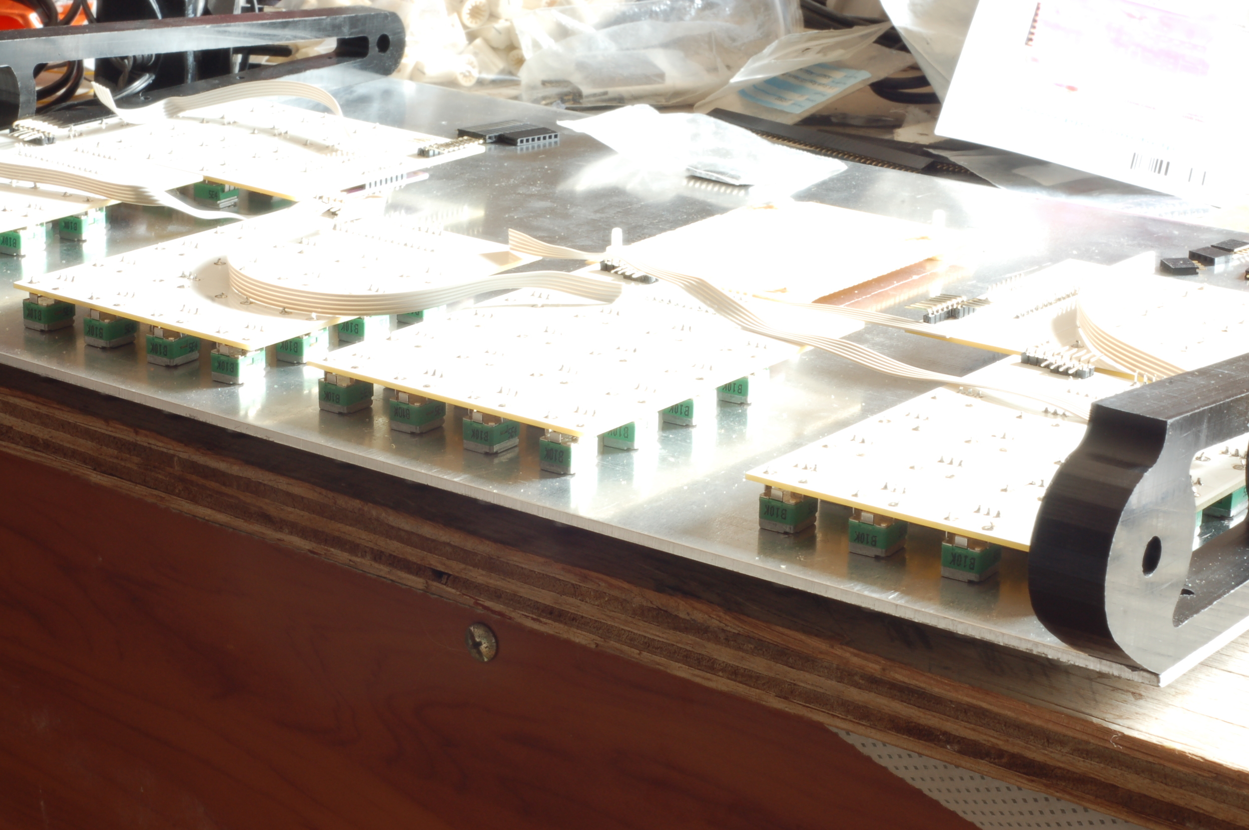
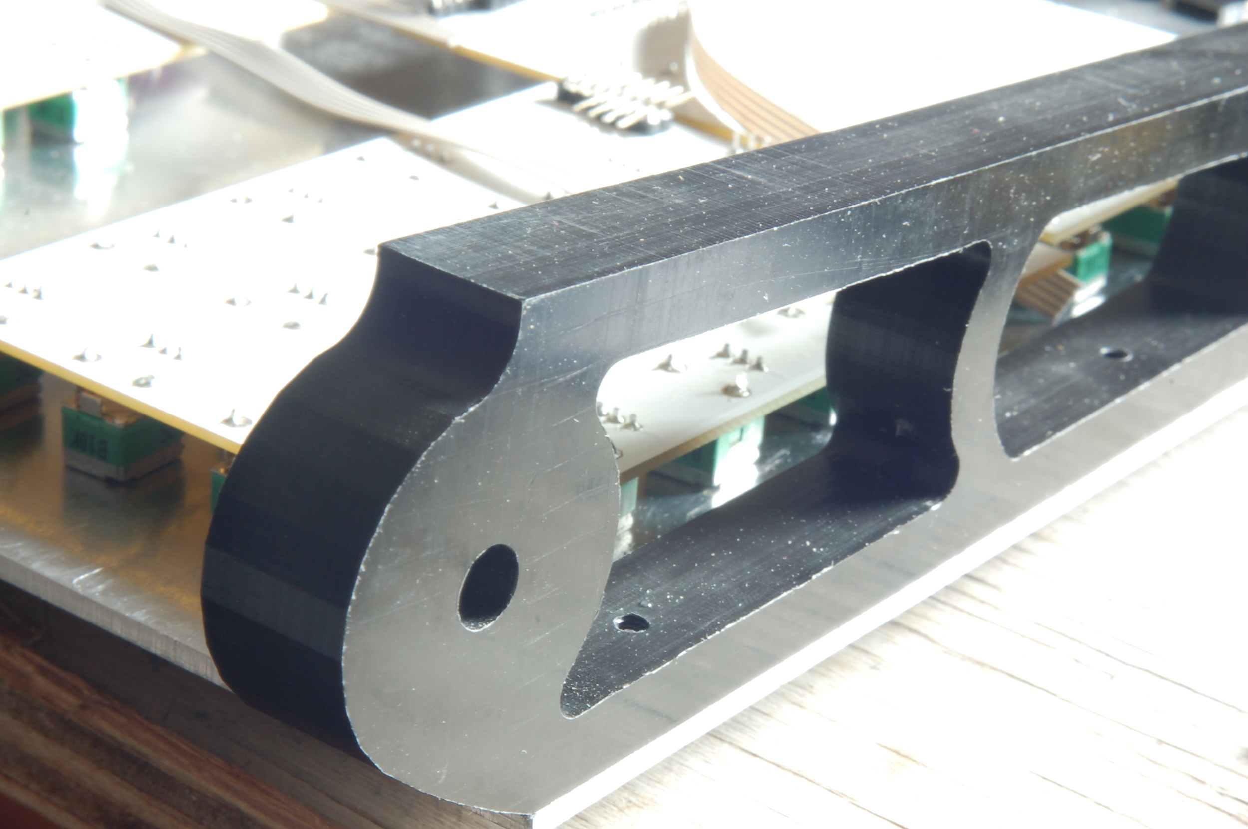
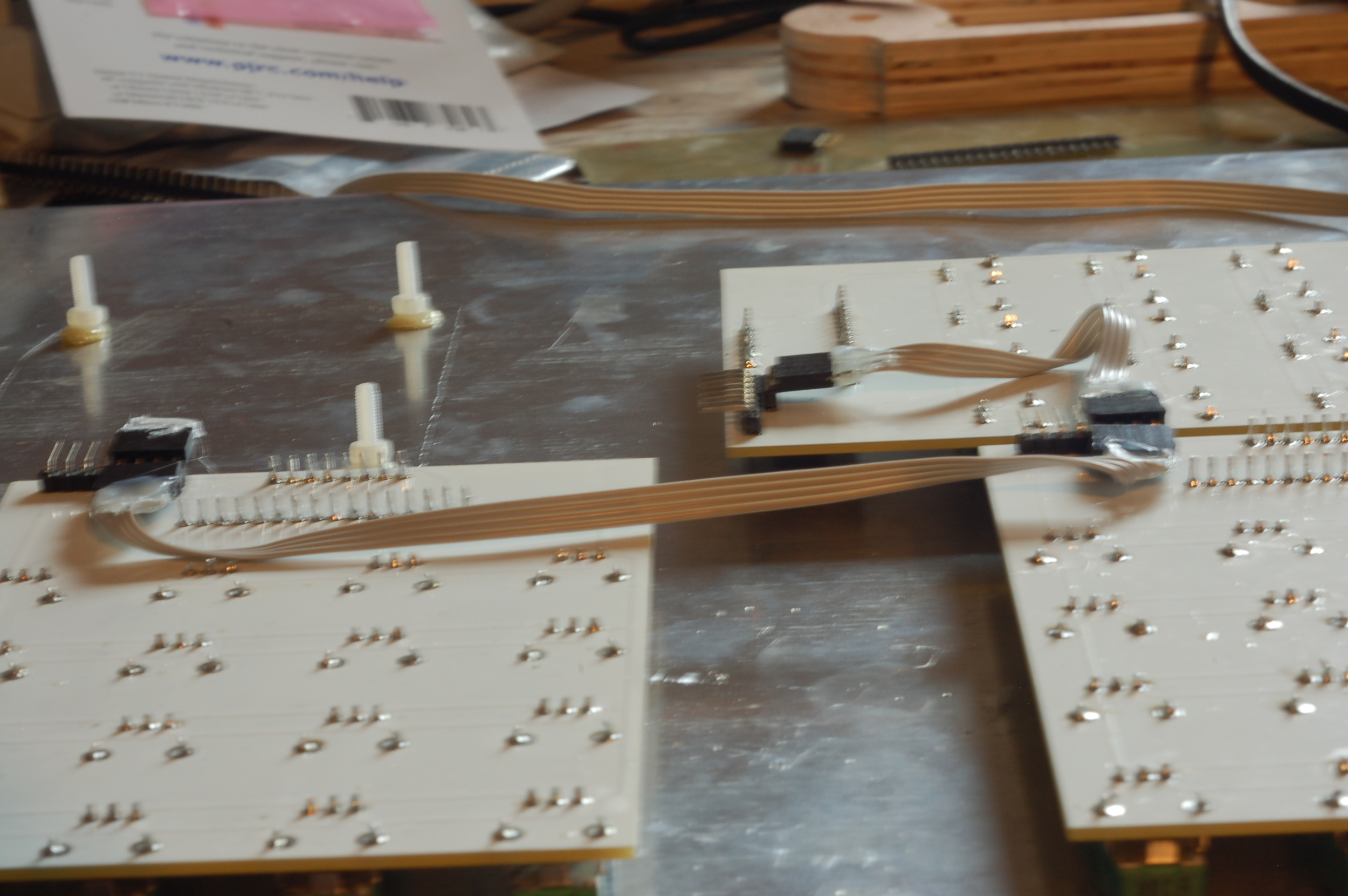
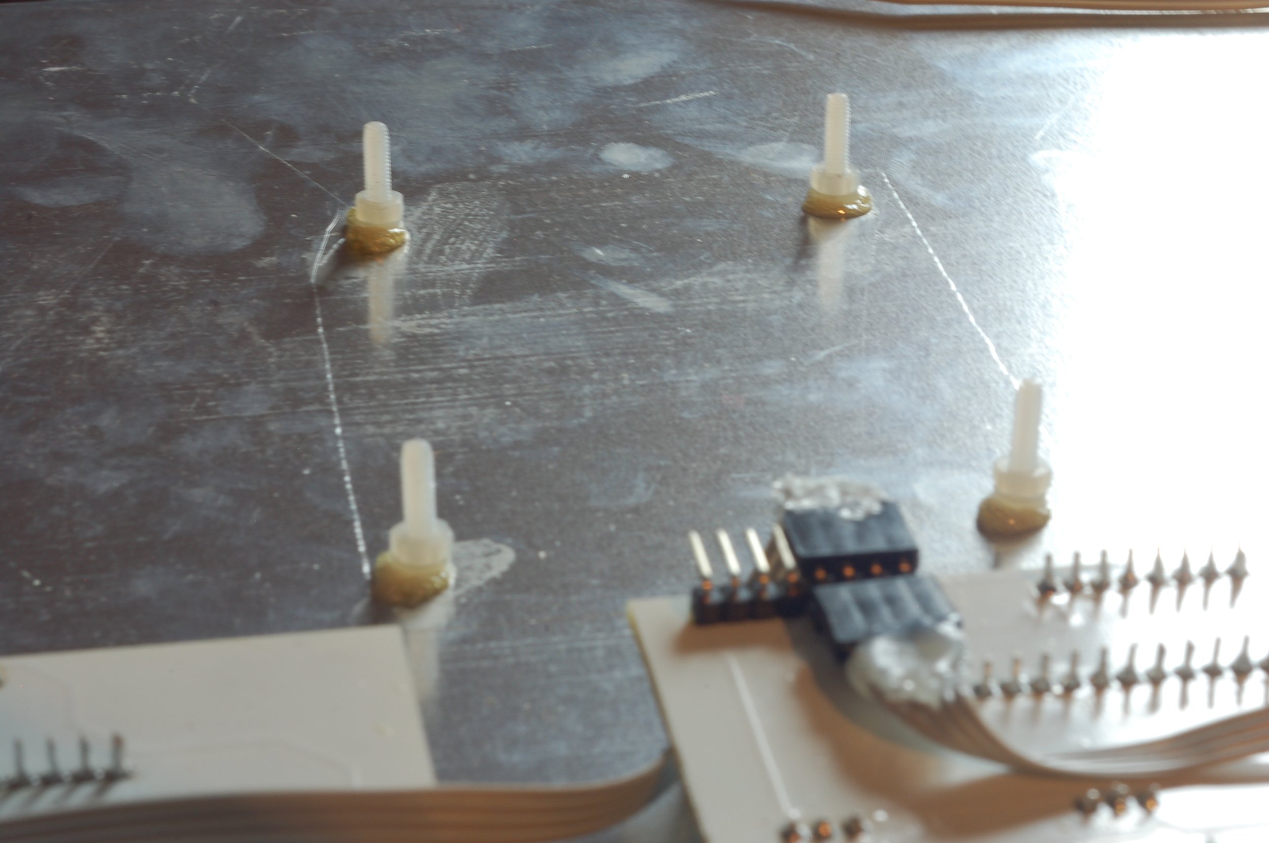
One element that I was very concerned with during the design of this project was the sheer amount of wiring that may be required and was very careful to try to minimise this as much as possible. For this reason I chose to design the main PCB's with panel mounted pots, as you can see in the below image. Since each potentiometer needs three connections, and we have 96 potentiometers in this project, this adds up to a great deal less wiring to do, something I am very glad about. To further minimise wiring the Multiplexer IC's were designed to fit to the PCB also. Each PCB holds 16 pots and a 16 channel multiplexer. Again this reduces wiring significantly and keeps things nice and tidy.
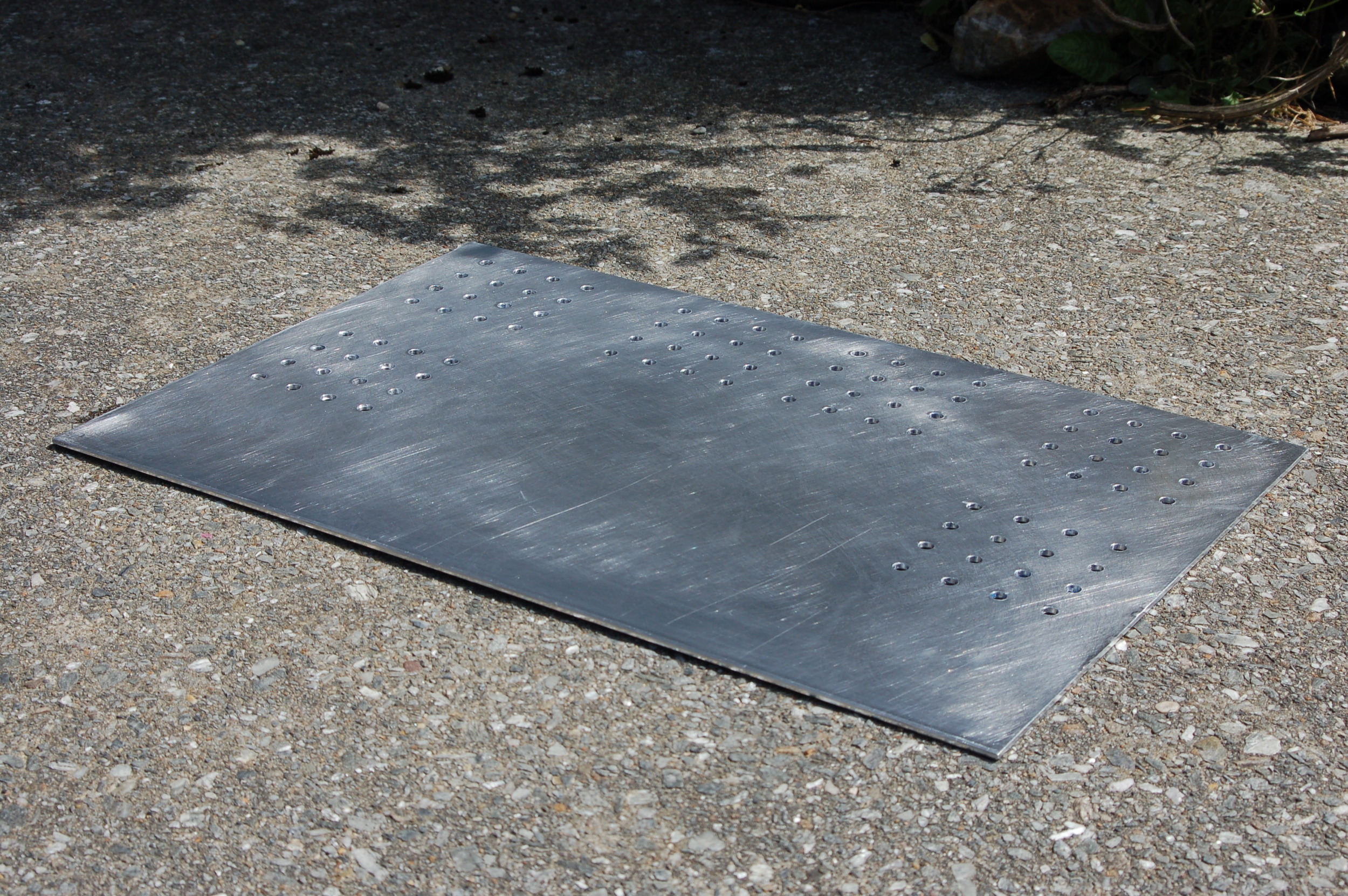
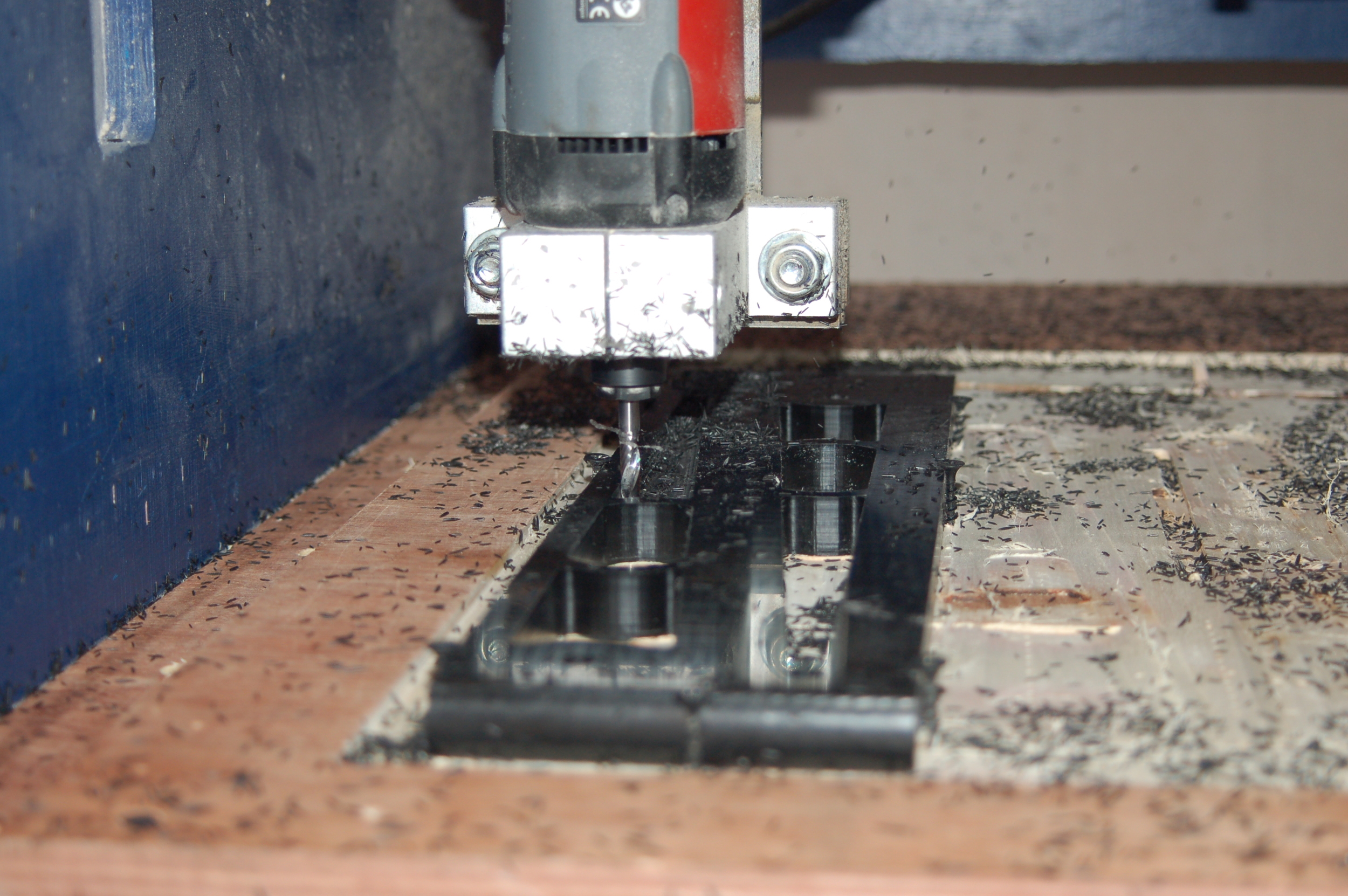
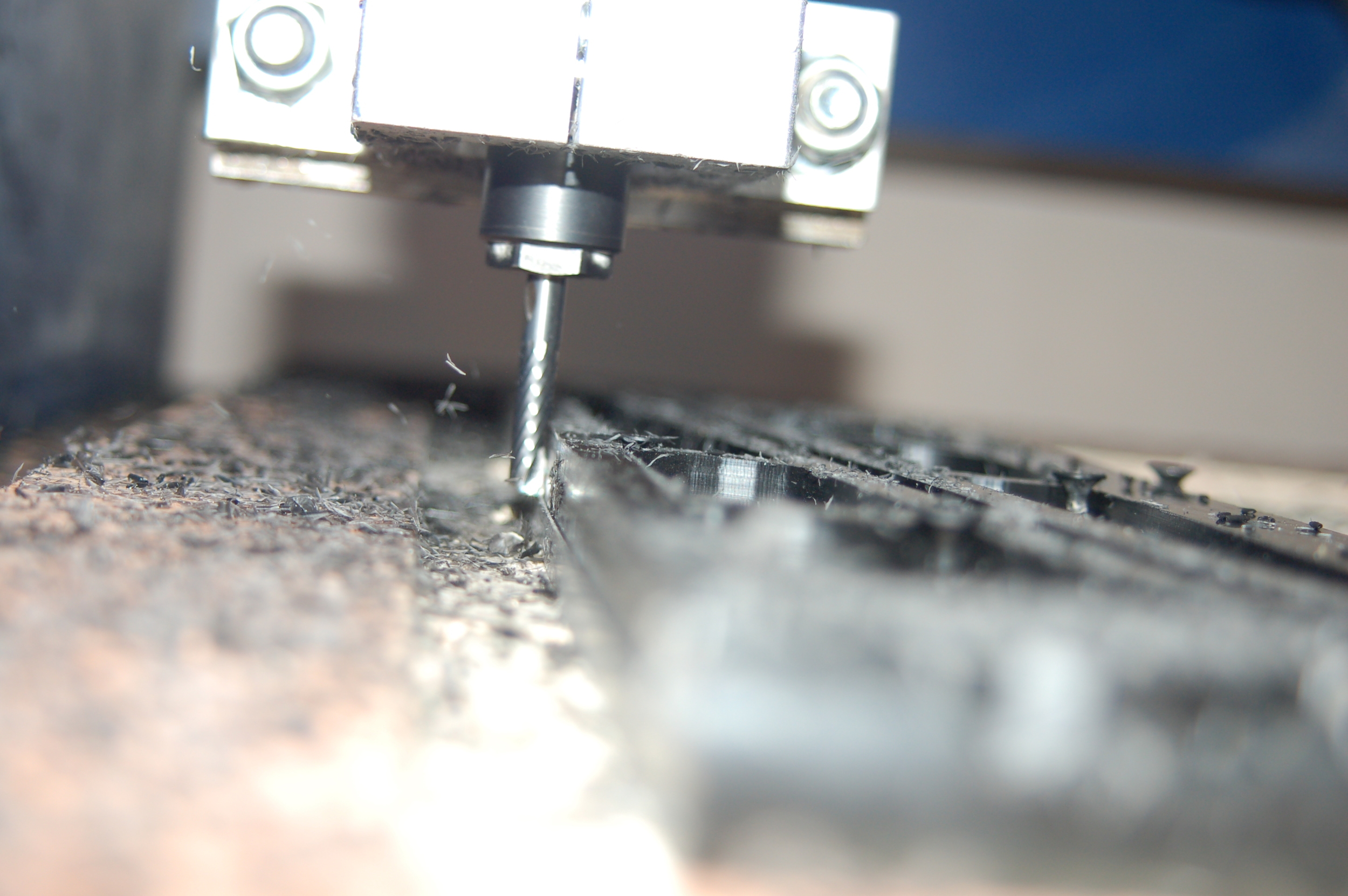
CAM
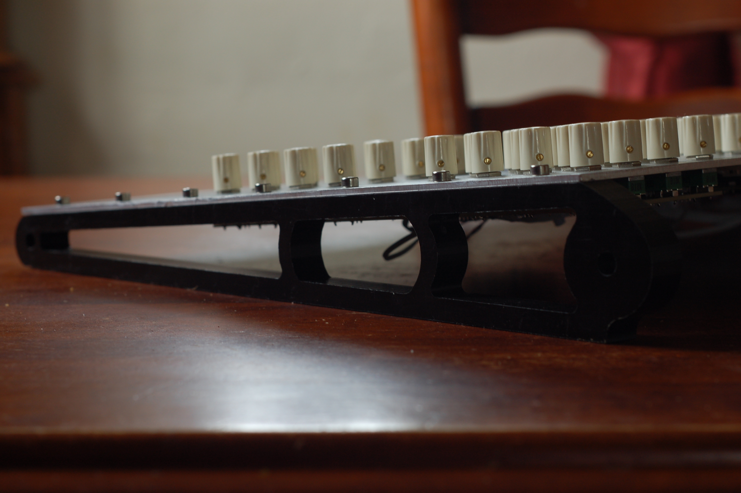
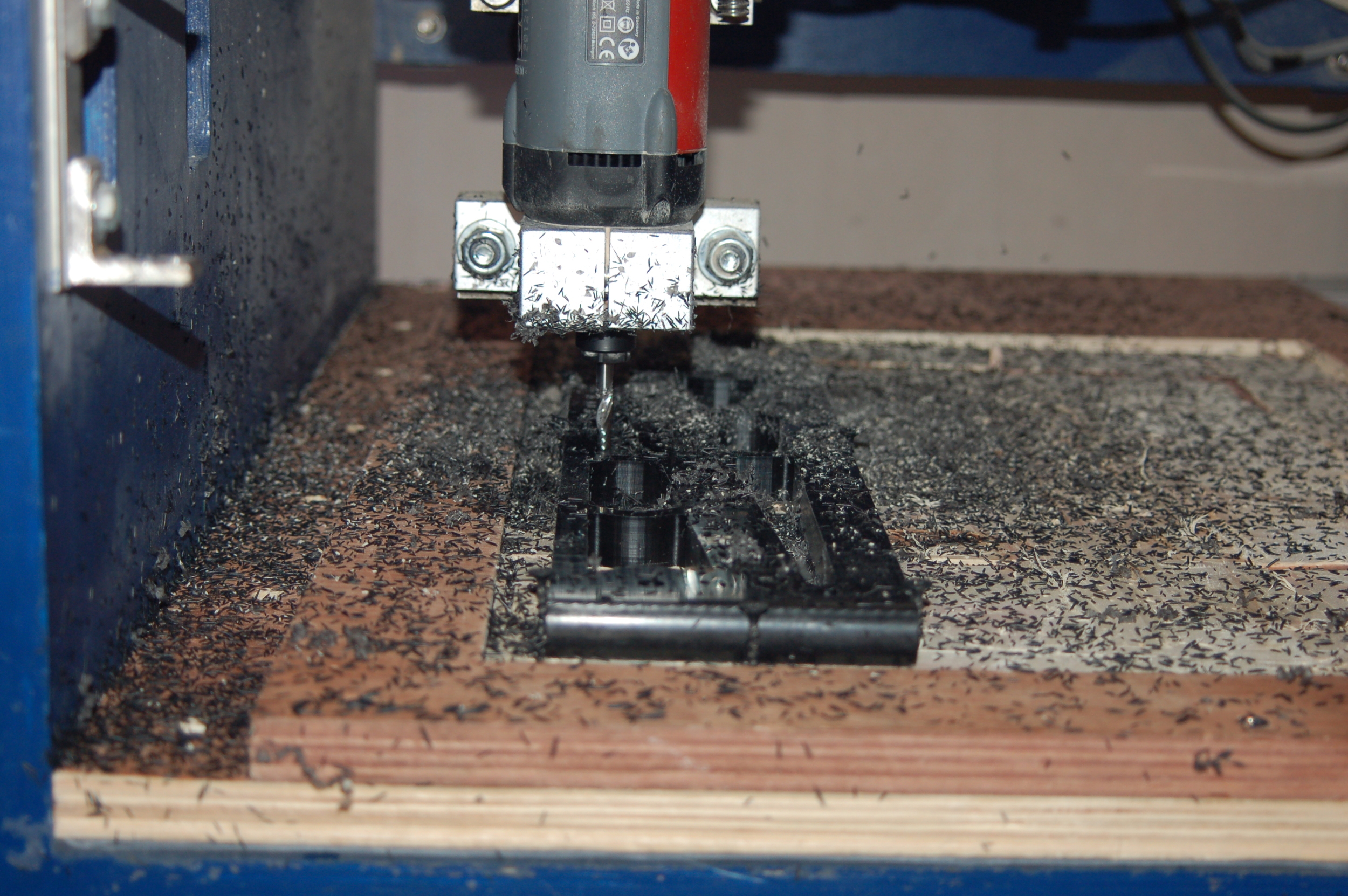
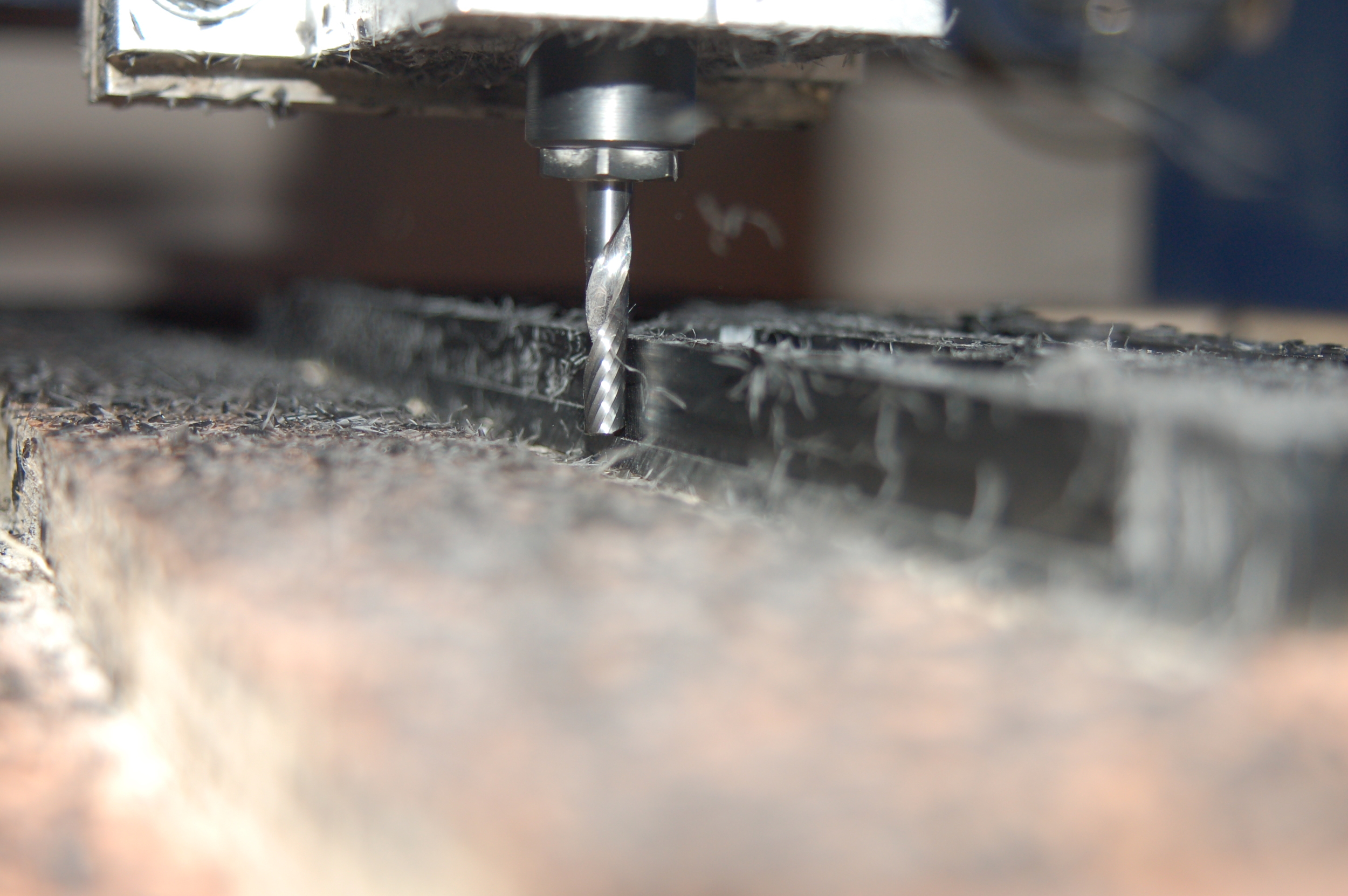
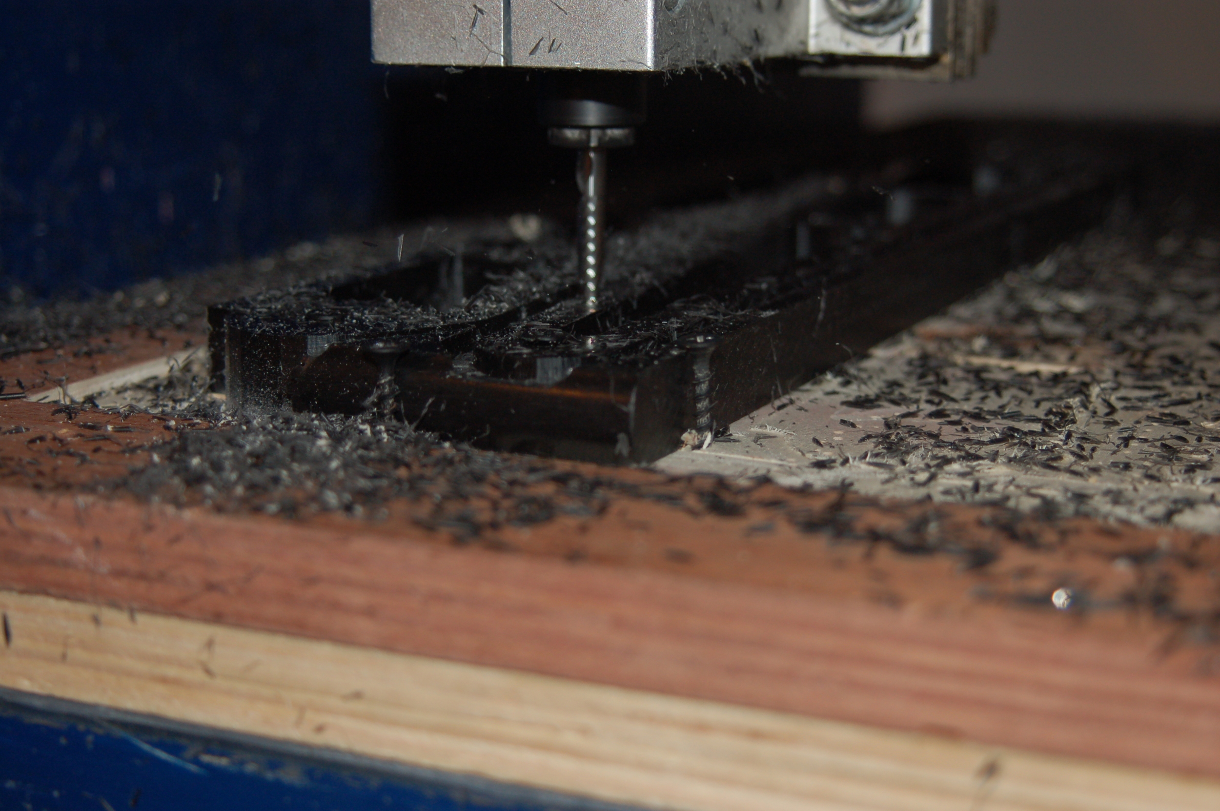
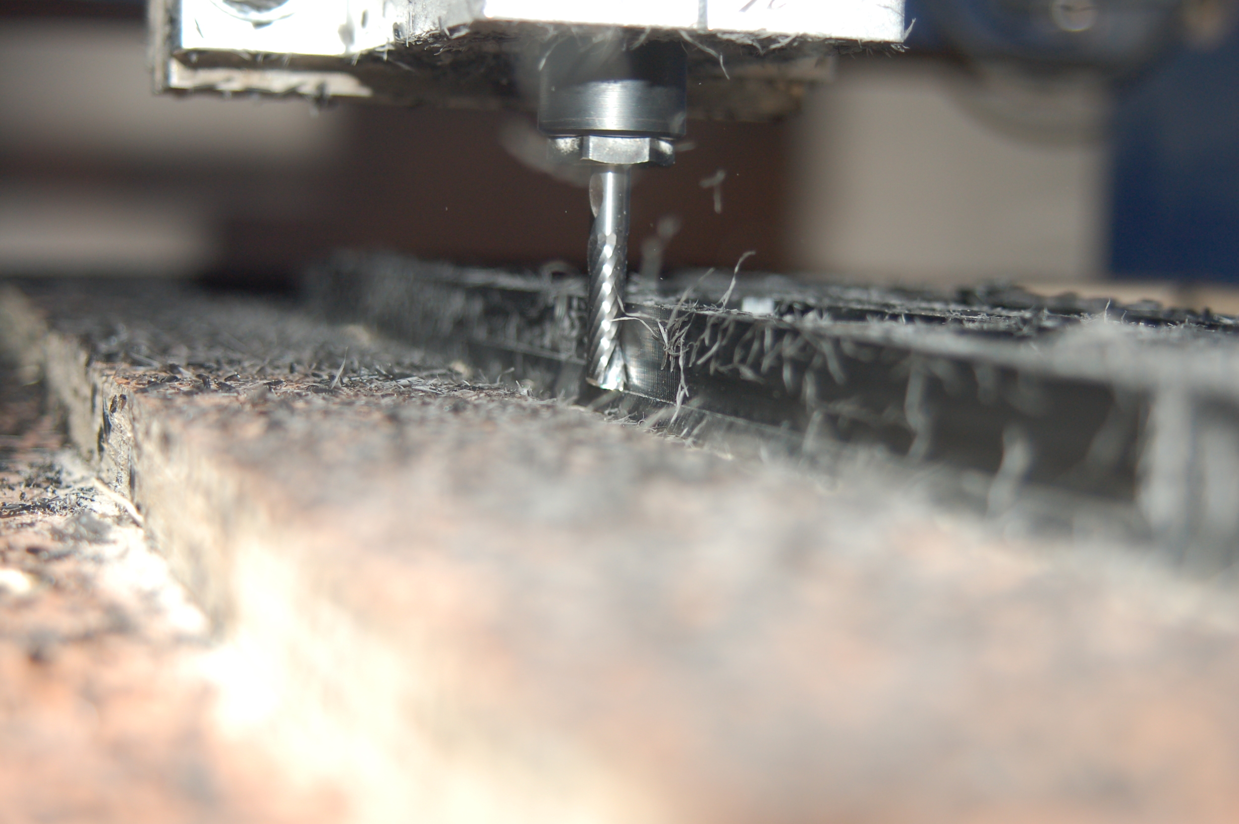
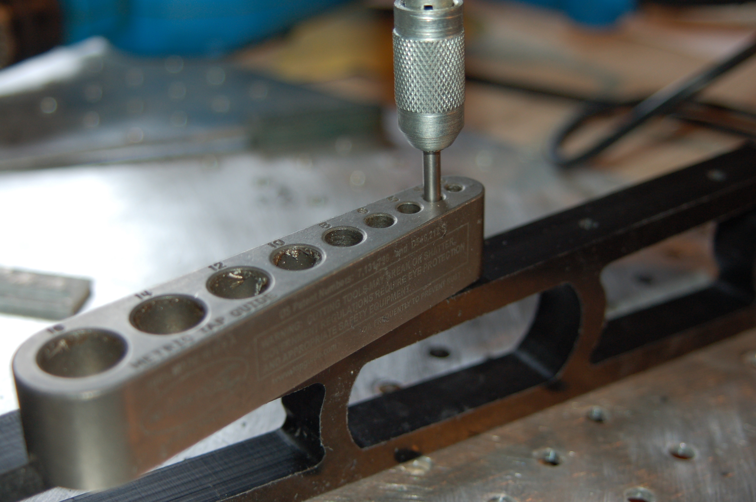
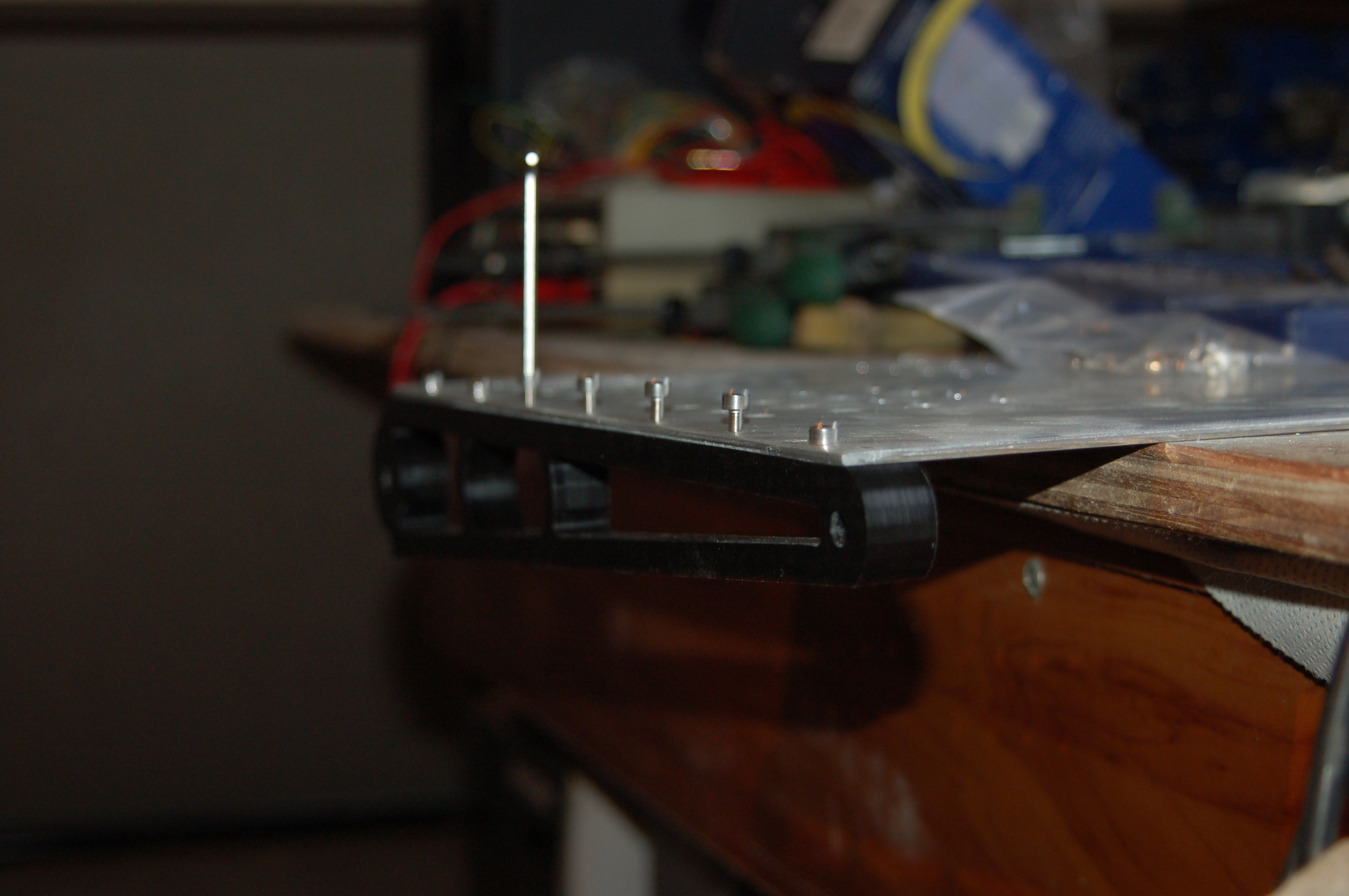
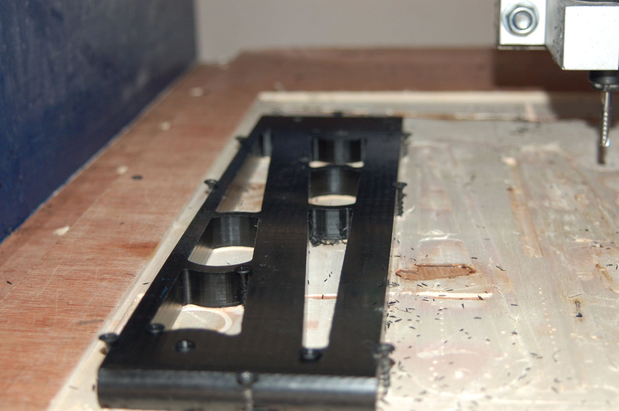
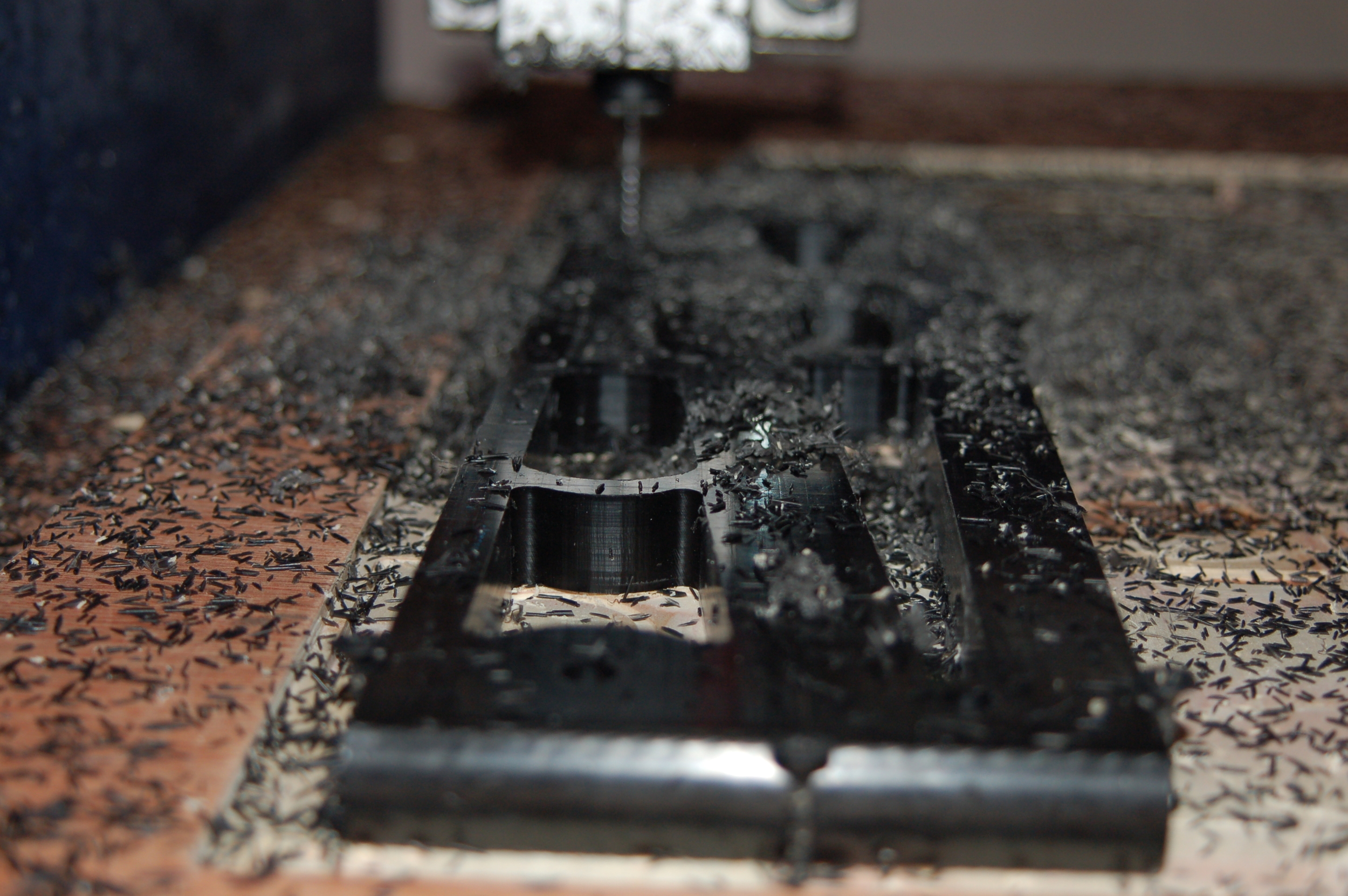
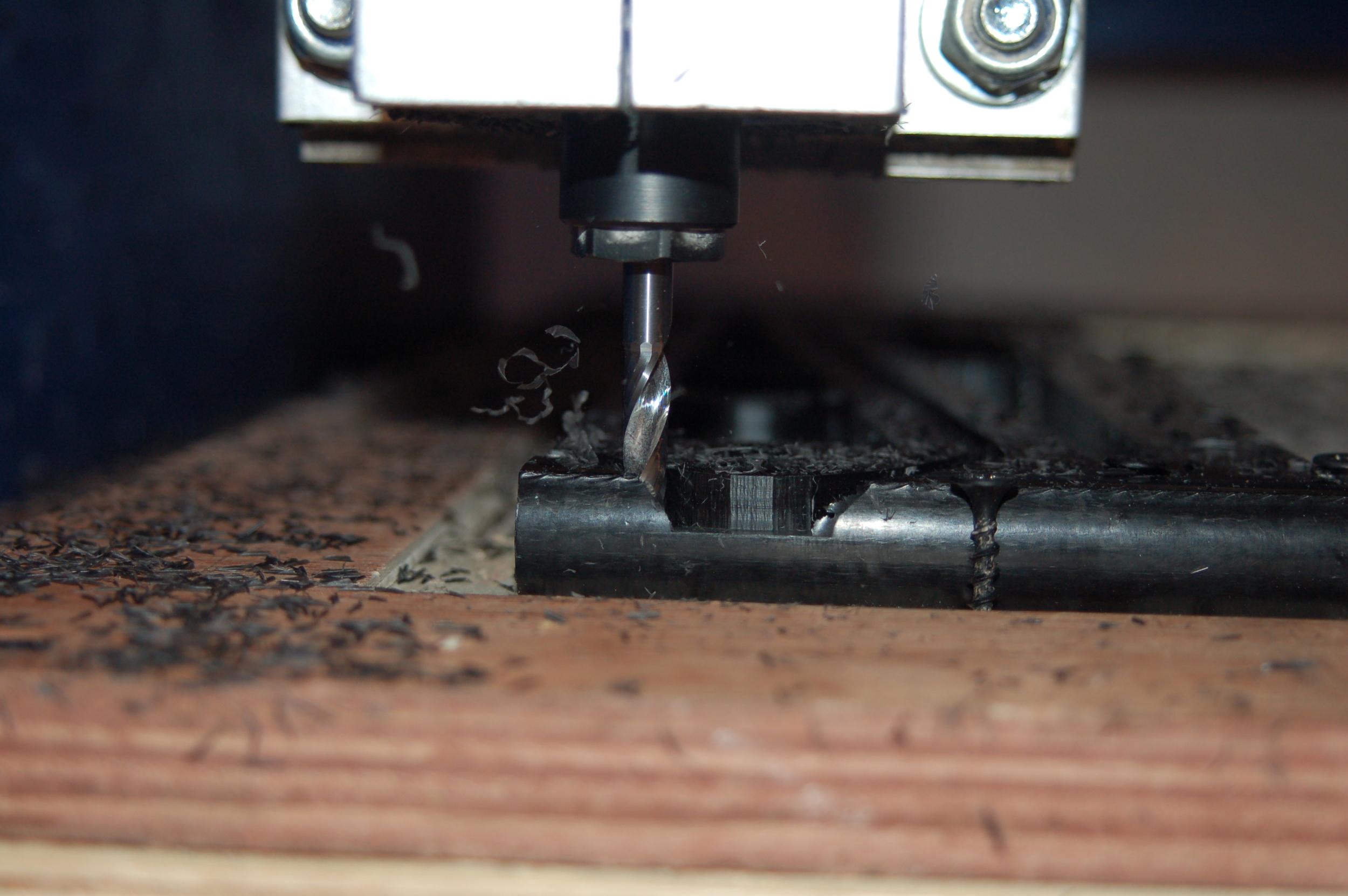
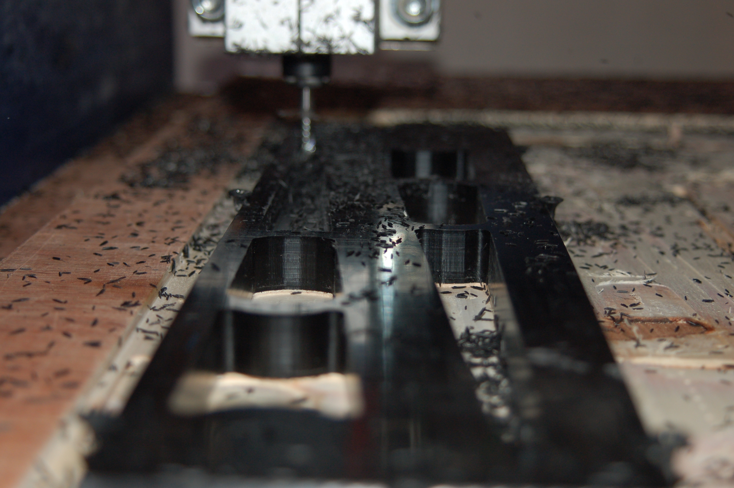
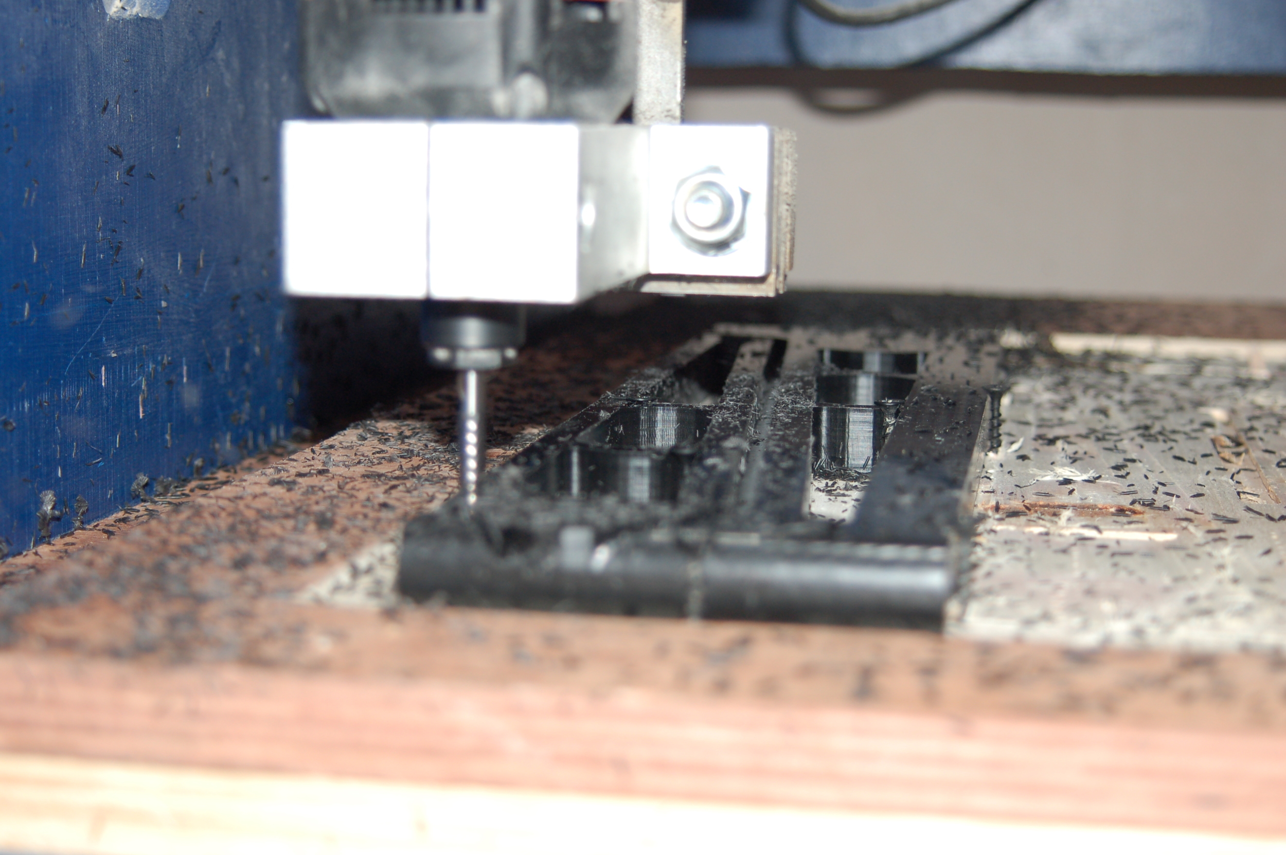
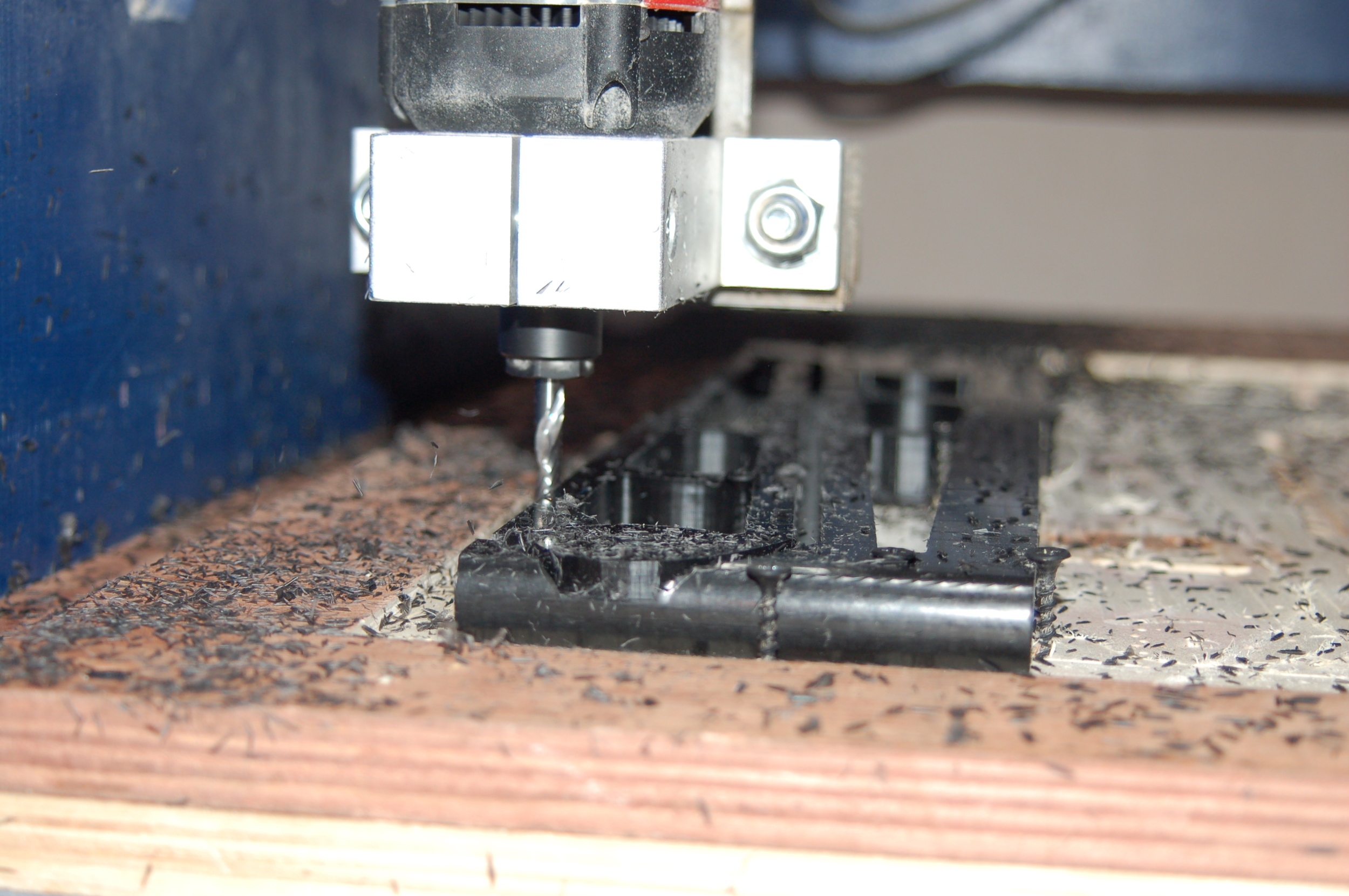
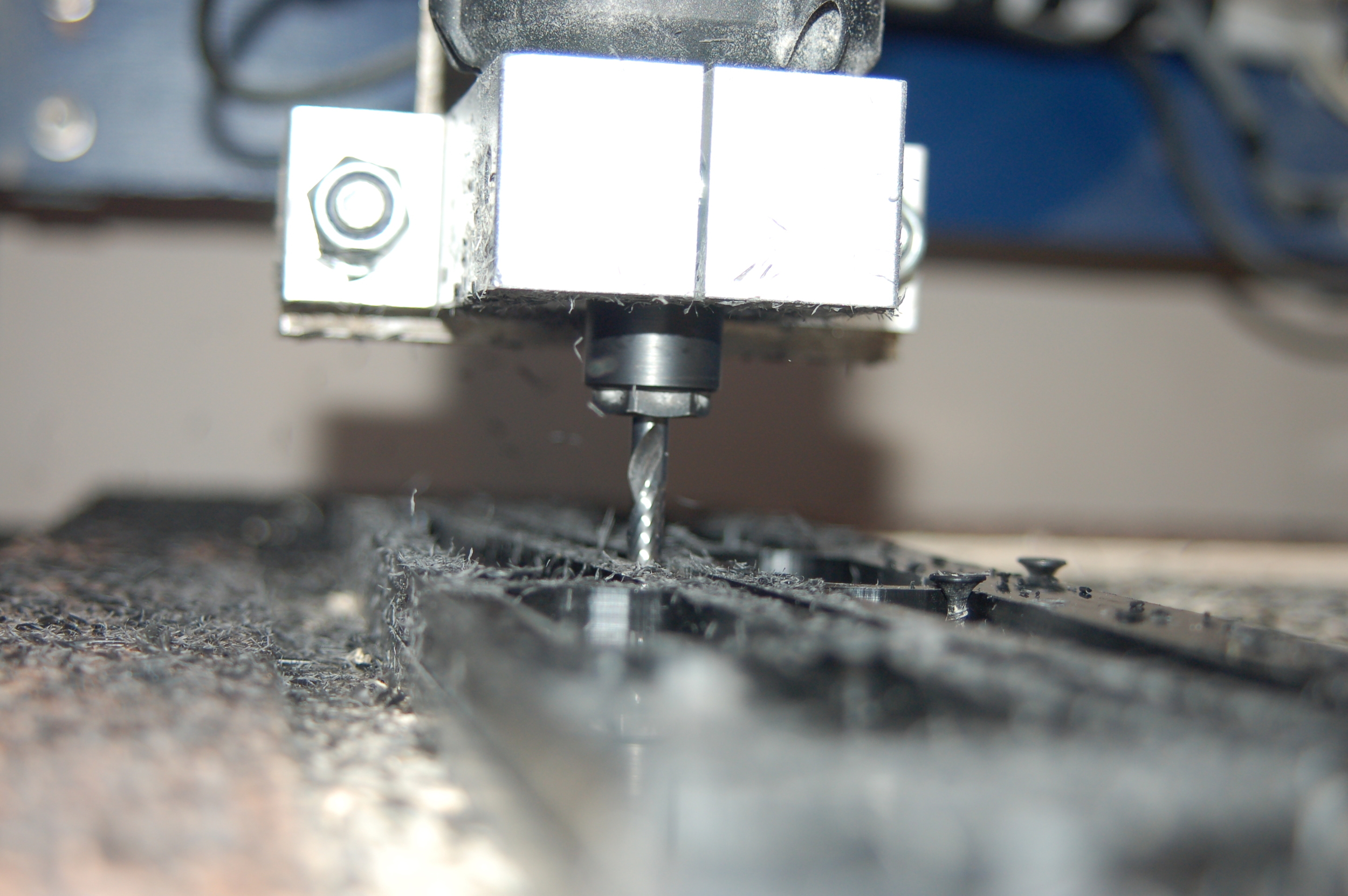
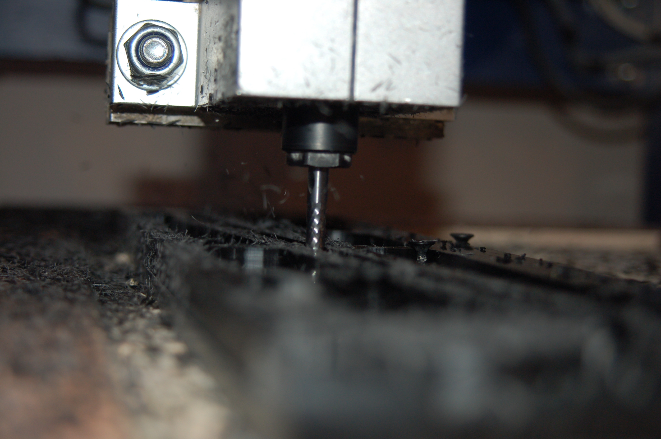
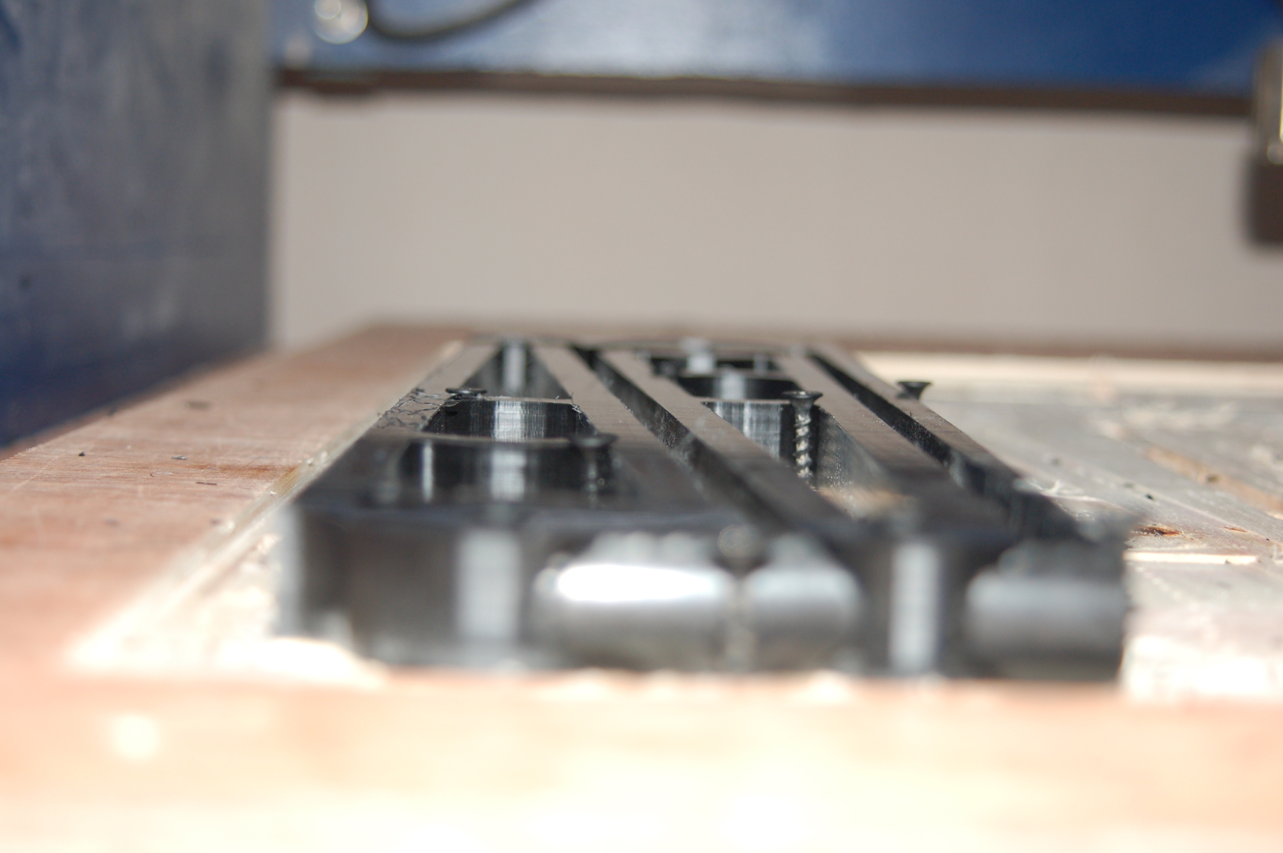
Following the design process the Sketchup file was broken down into individual elements for production via CNC. Below we can see a test Milling of the Side elements which were prototyped, along with the front panel, from plywood and eventually milled from Delrin (machinable plastic) and Aluminium respectively.
Test Milling
Test rendering of the milling operation for the Uberdeck sides.
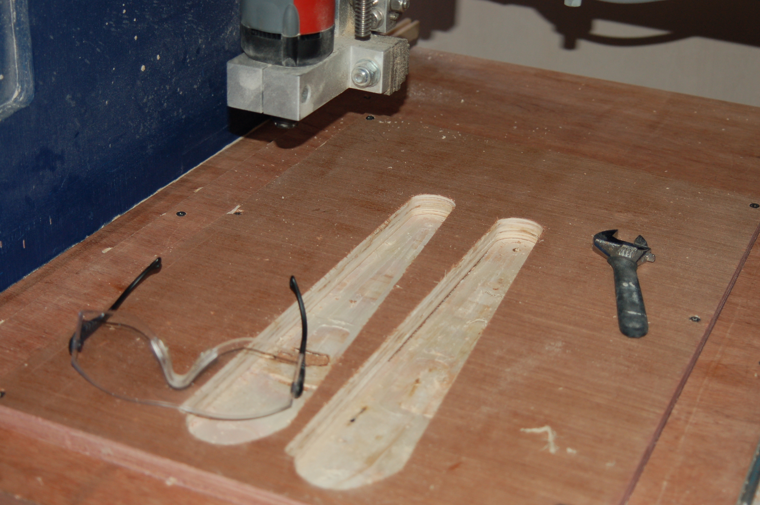
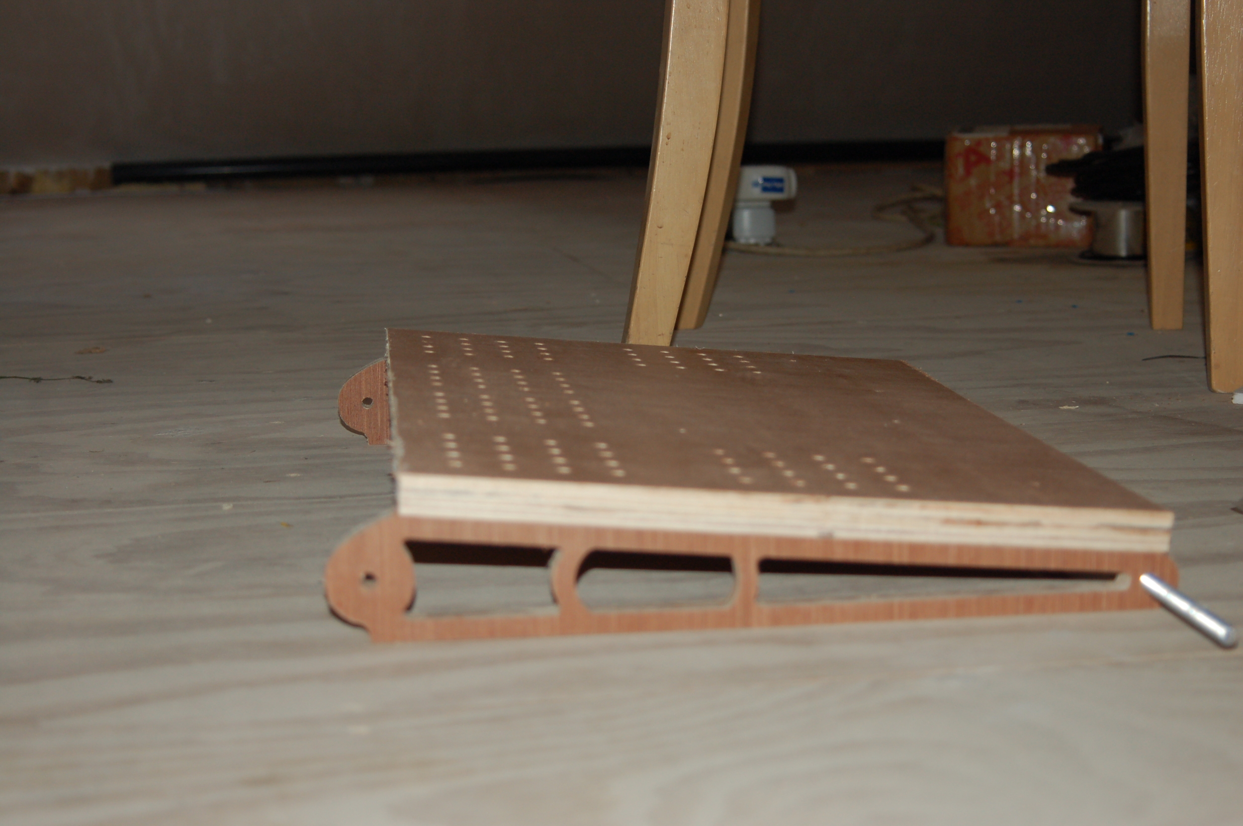
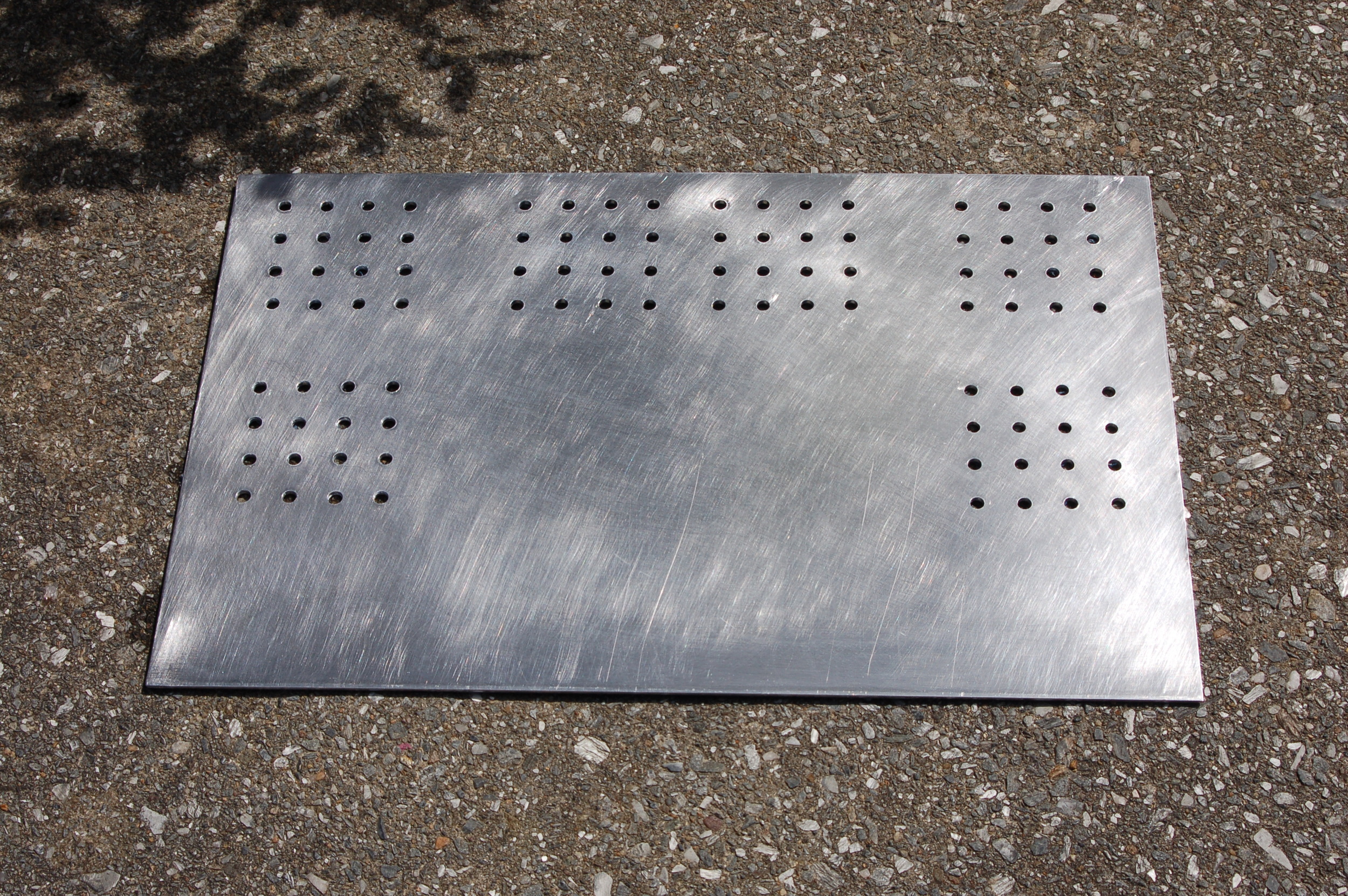
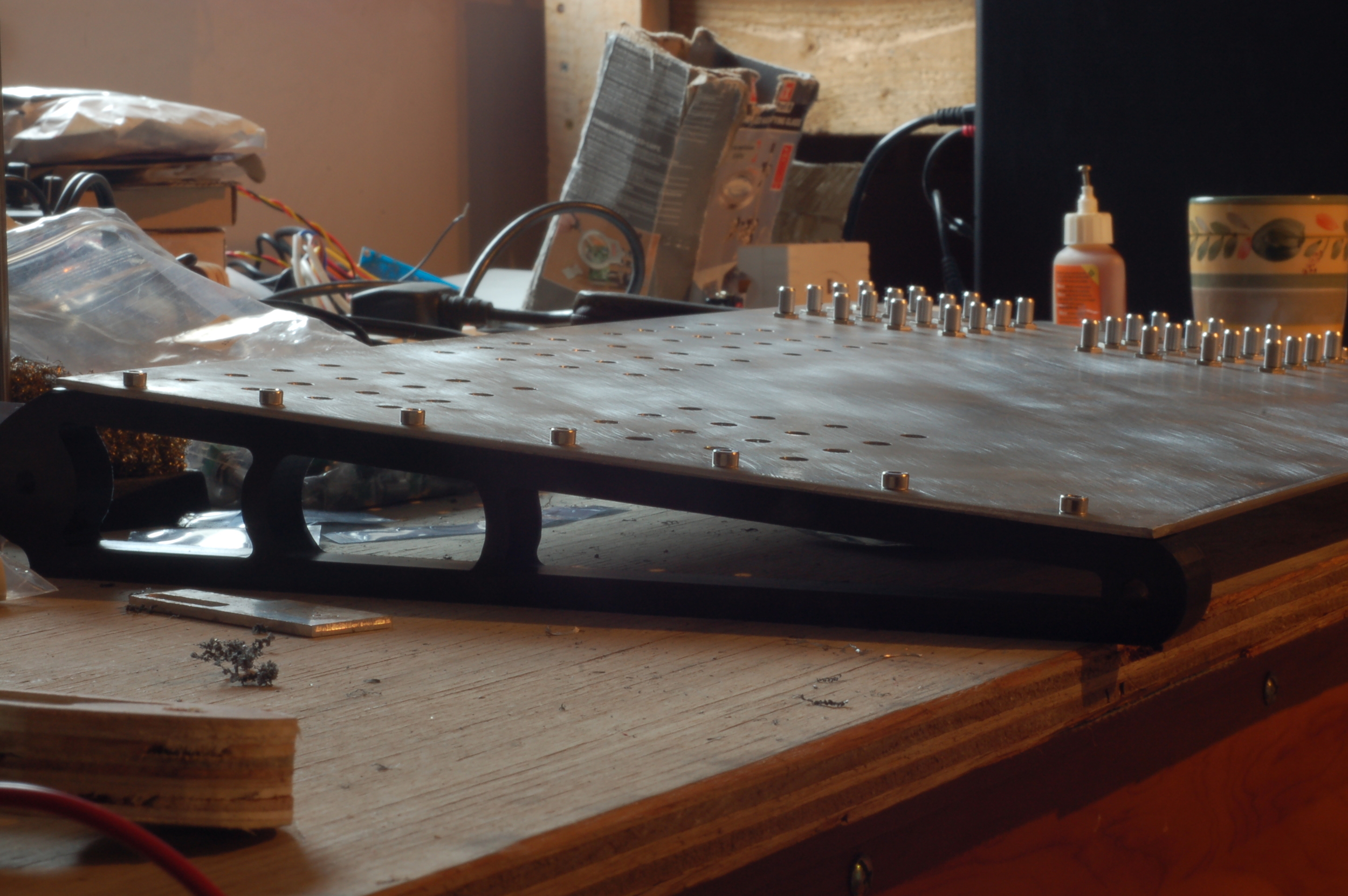
Once the mock-up was complete and I was happy that everything would fit as is should I went ahead and milled the front panel and the side parts on the CNC. Once the side elements were machined they were threaded to allow them to be bolted to the front panel.


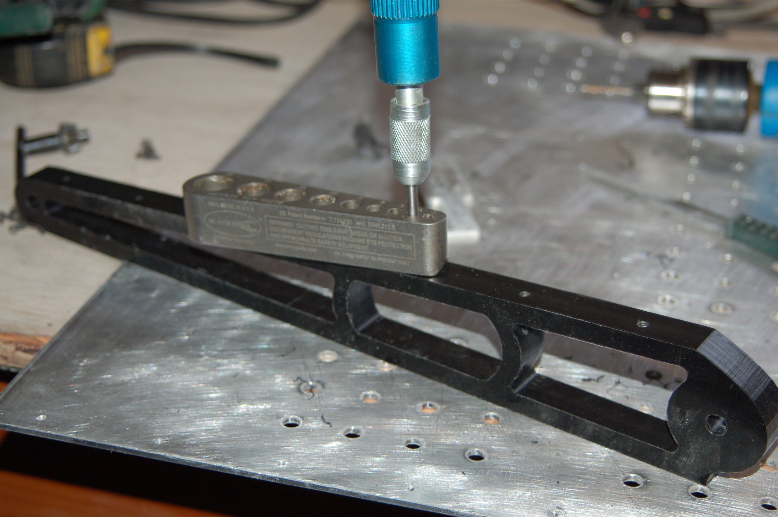
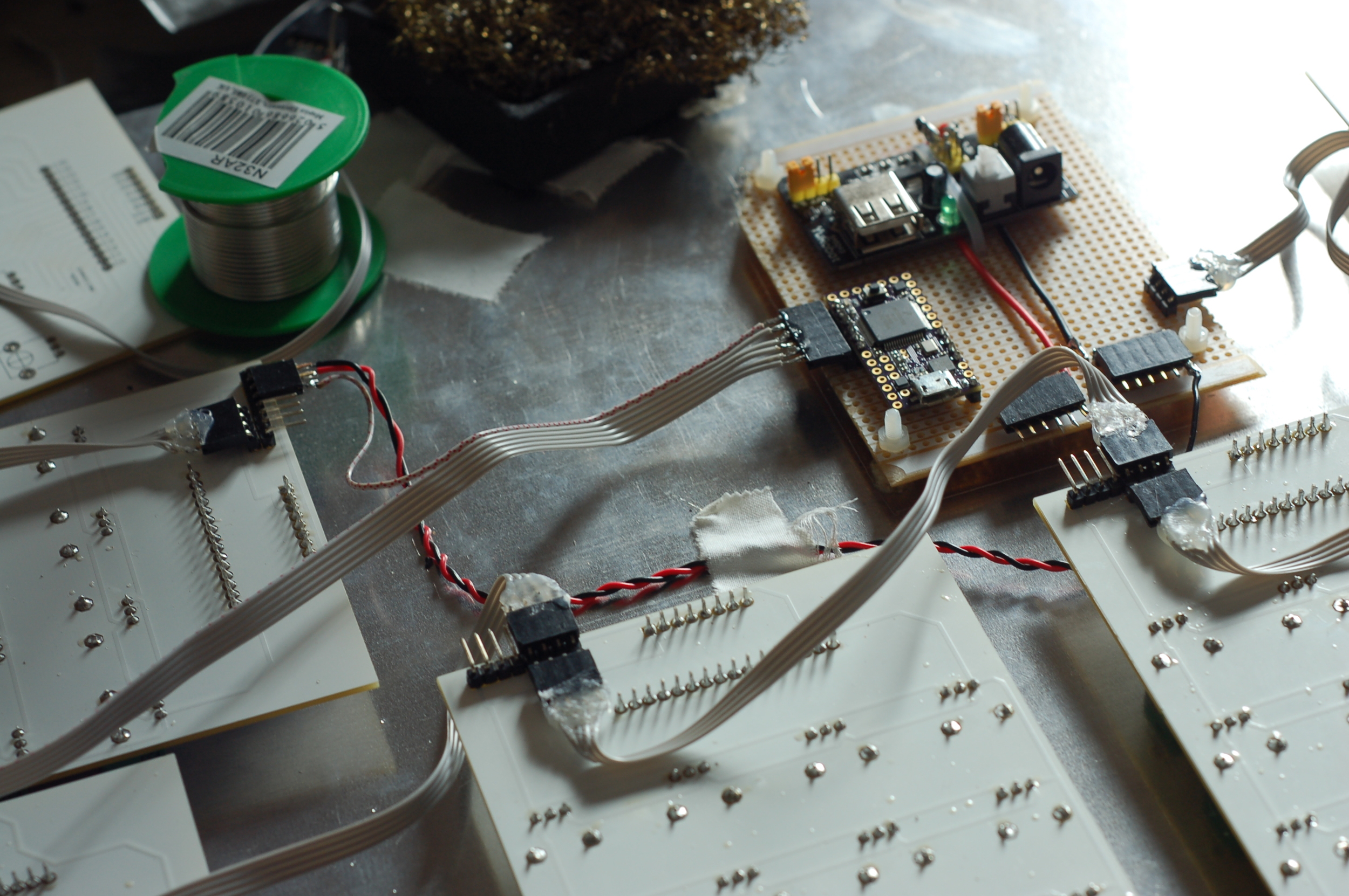
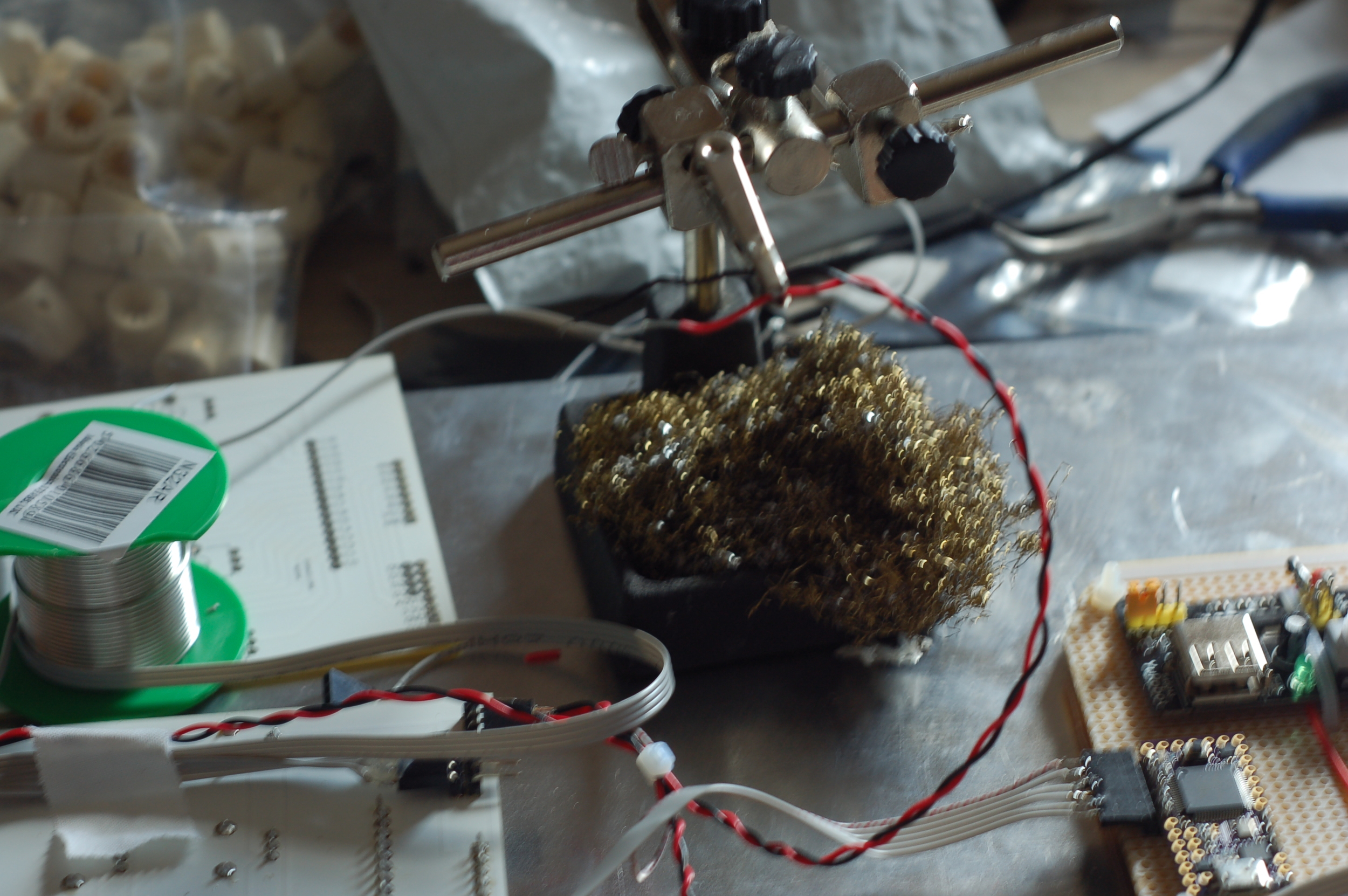
Construction Montage


Code
/* ------------------------------Uber Deck beta-----------------------------------------

Code to allow 96 pots to be read and their values transmitted via USB MIDI CC messages.
CD74HC4096 Multiplexers each read 16 potentiometers, 6 chips total for 96 pots.
Teensy 3.1 is the brains of the operation and this code employs the teensy usbMIDI library
to produce the MIDI Control Change messages and to transmit these
MIDI CC messages via a class compliant USB MIDI protocol.

-------------------------------No driver required!--------------------------------------

The Teensy MIDI CC Function is in the format: usbMIDI.sendControlChange(control, value, channel)
--------------------------------------------------------------------------------------*/

//Uses Analog inputs A0 through to and including A5 (six, one for each multiplexer)
//...and four digital address pins (ax, bx, cx, dx) for the binary counting to 16 (0-15).

//------------------------------------------------------------------------------------//
//----------------------John Harding - 2015 - Steal This Code-------------------------//
//------------------------------------------------------------------------------------//


//--------------------------------Constants-------------------------------------------//
const int channel = 1;
const int ax = 2; //digital address pin a
const int bx = 3; //digital address pin b
const int cx = 4; //digital address pin c
const int dx = 5; //digital address pin d

//-----------------------------------------------------------------------------------//

//--------------------------------Variables------------------------------------------//

byte data; //storage for adjusted pot readings, these must fit into a single byte, 0-127
byte checker[96] = { 0 }; //array of 96 values to store changes vs previous loop.

//-----------------------------------------------------------------------------------//

//---------------------------------Setup---------------------------------------------//

void setup() {
//set Mx address pins as outputs
pinMode(ax, OUTPUT);
pinMode(bx, OUTPUT);
pinMode(cx, OUTPUT);
pinMode(dx, OUTPUT);
//initialise Mx address pins to zero
digitalWrite(ax, LOW);
digitalWrite(bx, LOW);
digitalWrite(cx, LOW);
digitalWrite(dx, LOW);


//Serial.begin(115200); //used for testing
}

//-----------------------------------------------------------------------------------//

//-----------------------------------Loop--------------------------------------------//

void loop() {
  elapsedMillis wait; //starts time counter at zero
    while (wait <= 1) { //wait until (at least) 1 milliseconds has passed

      int i; //integer variable for iteration through Mx Pins 0-15
      int j; //integer variable for iteration through analog inputs A0-A5

      for (i=0; i <16; i++) { //for each input of the Mx..
          // set control pins on the multiplexers using binary counting in bitwise operations
          digitalWrite(ax, (i&15)>>3);//bit4
          digitalWrite(bx, (i&7)>>2);//bit3
          digitalWrite(cx, (i&3)>>1);//bit2
          digitalWrite(dx, (i&1) );//bit1
          //delayMicroseconds(1); //delay 1usec (1000ns) for Mx to stabilise, optional

              // read the analogue inputs A0 - A5, scale readings to fit into MIDI range 0-127.
              for(j=0; j<6; j++){
                  data = (analogRead(j)) /8; //adjusted based on analog read resolution (must fit into a byte)
                      if (checker[i+16*j] != data) { //if the read value differs from the previously read value (stored in array "checker")
                      usbMIDI.sendControlChange(i+16*j, data, channel); //Send MIDI CC commands via USB Midi.
                        }
                  checker[i+16*j] = data; //update "checker" array position with currently read value
                  wait = 0; //reset time count to zero
                  }
        }
    }
    // MIDI Controllers should discard incoming MIDI messages.
    while (usbMIDI.read()) {
  }
}
//-------------------------------------//
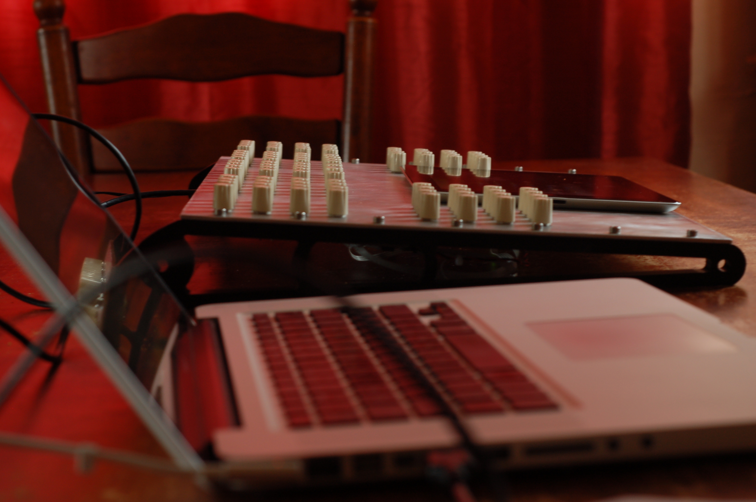
The Result
The final unit exceeds my expectations by a long way; it is responsive, lightweight and suits my needs perfectly. Now I need to spend some time with it but I'm sure it will be extremely useful. If you have any questions let me know via my Contact form to the left.
Until next time...